
Static desalter simulator

a simulator and desalter technology, applied in the field of small-scale simulation, can solve the problems of crude oil forming an undesirable, oil loss, corrosion of oil processing equipment,

Inactive Publication Date: 2012-06-07
GENERAL ELECTRIC CO
View PDF8 Cites 2 Cited by
  • Summary
  • Abstract
  • Description
  • Claims
  • Application Information

AI Technical Summary

Benefits of technology

[0010]In one aspect, the invention is directed to a small-scale static simulator for crude oil refinery desalters. The desalter simulator includes an oil bath, a portion of which is made of a transparent material, a heater / circulator configured to control the temperature of the oil bath and an emulsion-forming device. The desalter simulator also includes a plurality of mixing tubes, each mixing tube having a cap member with a blending assembly configured to work with the emulsion-forming device to emulsify an oil / water mixture contained in the mixing tube. A tube-holding rack is received in the oil bath. The tube-holding rack has a plurality of parallel plates, said plates having openings forming mixing tube receiving apertures. The desalter simulator includes at least one light source positioned adjacent to the oil bath, wherein the light source comprises an under light positioned beneath the oil bath configured to direct light into each of the mixing tubes located in the tube-holding rack, wherein the light source is directed through the transparent portion to aid in visualization and testing of the demulsification process. The desalter simulator also includes a power supply, wherein the plates of the tube-holding rack are connected to the power supply to form an electric grid adjacent the mixing tubes. In one embodiment, the desalter simulator also includes an imaging device used to record the separation of the oil and water in the mixing tubes.

Problems solved by technology

Liquid hydrocarbon phase, such as crude oil, naturally contains a variety of contaminants that have detrimental effects on process equipment and in the operation of a refinery.
The presence of salts, especially chlorides of Group I and Group II elements of The Periodic Table of Elements, causes corrosion of oil processing equipment.
One problem encountered with dewatering and desalting is that some crude oils form an undesirable “rag” layer comprising a stable oil-water emulsion and solids at the water-oil phase boundary in the desalter vessel.
Rag layers at the water-oil phase boundary result in oil loss and reduced processing capacity.
The additives reduce the effective time required for good separation of oil, solids, and water.
These methods have proven to be useful but they often fail to adequately simulate many critical parameters of a desalter and have been of limited use particularly in heavy oils or systems that have a propensity to develop rag layers.

Method used


Image

  • Static desalter simulator
  • Static desalter simulator
  • Static desalter simulator

Examples


examples

[0026]mix valve 10 psi: Select 10,000 rpm / 2 sec

[0027]mix valve 20 psi: Select 10,000 rpm / 3 sec

[0028]mix valve 13 psi: Select 13,000 rpm / 2 sec

[0029]mix valve 16 psi: Select 16,000 rpm / 2 sec

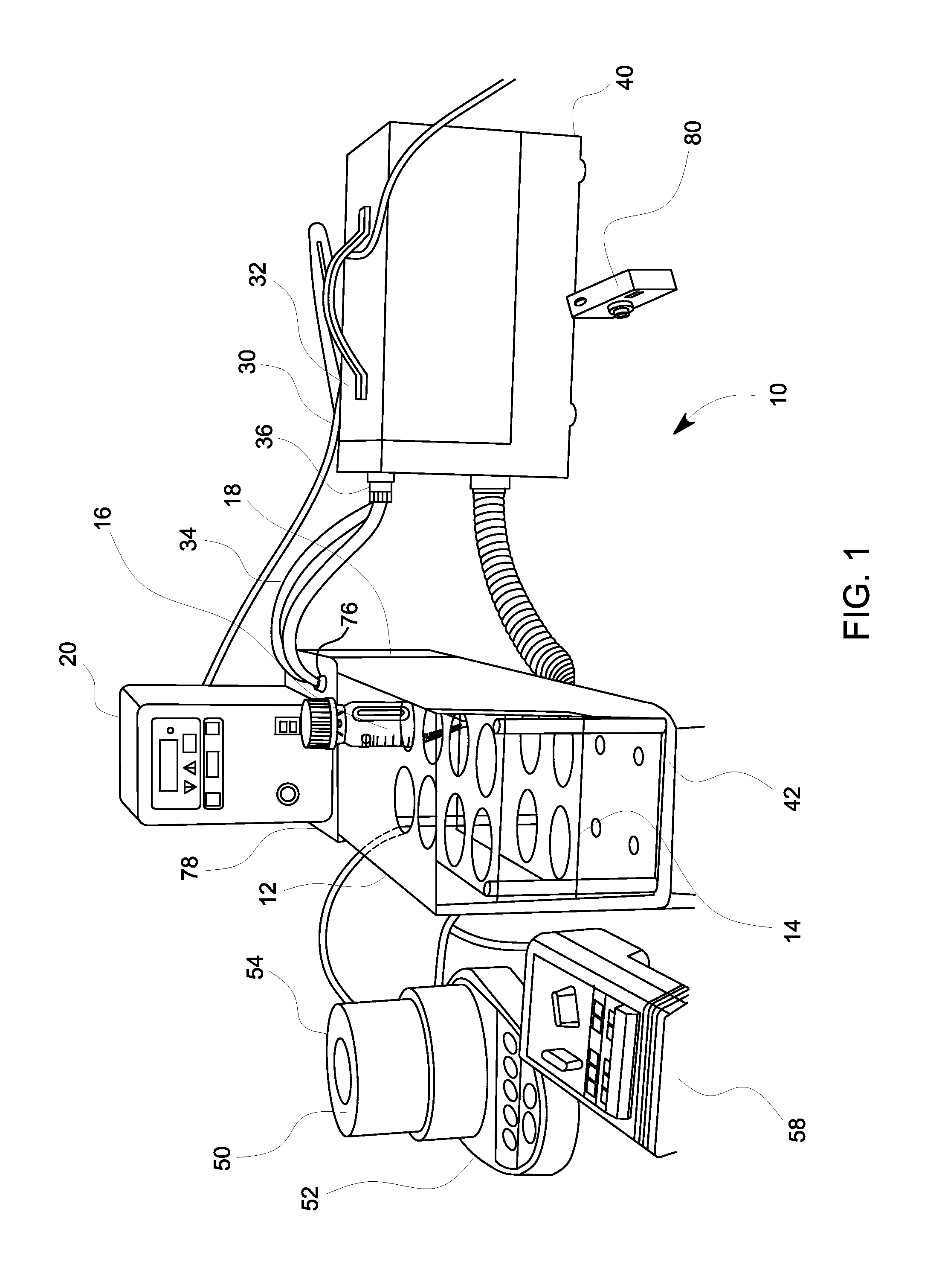
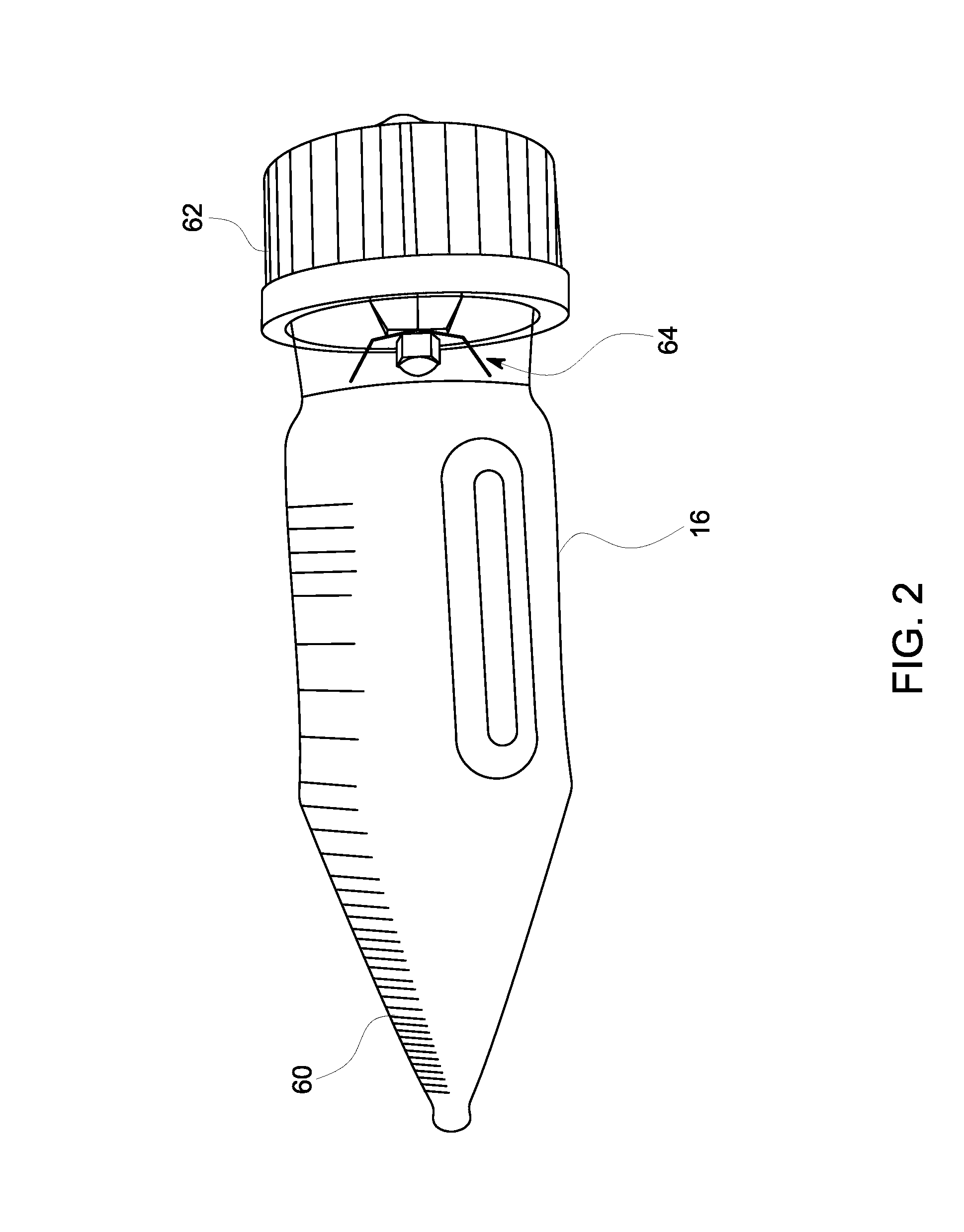
[0030]The mixing tubes 16 are desirably made of glass since this permits visible inspection and prevents any significant electrical conduction. The mixing tubes 16 are of sufficient thickness to not break under normal usage in the desalter simulator apparatus 10. Two millimeters or more of thickness is typically sufficient. The volume of the tubes can vary but the size and shape must match up with the tubular recesses in the tube rack 14. About 100 ml or more is typical. FIG. 4 illustrates one desirably embodiment of a mixing tube 16. The mixing tube 16 has a graduated tip 60 rather than a conical tip to improve the precision at which measurements may be read. Sides of the mixing tube 16 have Morton indentations to promote better agitation of the oil / water mixture.

[0031]The mixing tubes 16 accept a...

example

[0039]In order to assess the emulsion-breaking efficacy of the candidate materials, simulated desalter tests were undertaken using the desalter simulator apparatus 10. The desalter simulator apparatus 10 comprises the oil bath 12 reservoir provided with a plurality of mixing tubes 16 dispersed therein. The temperature of the oil bath 12 can be varied to about 250° F. to simulate actual field conditions. The mixing tubes 16 are placed into an electrical field to impart an electrical potential through the test emulsions.

[0040]The conditions of the process were:

[0041]Process Temperature: 250° F.

[0042]Water Ratio: 5%

[0043]Mix valve pressure: 10 psi

[0044]Grids on

[0045]Pre-heat the oil bath 12 to 250° F.

[0046]The blender was set to 10,000 rpm, and the Timer for 2 seconds

[0047]5 ml of the wash water was added to the tube

[0048]95 ml of the crude was added to the tube. Treat the tube with oil-based chemical to oil phase.

[0049]The mixing tube was capped and placed into the pre-heated oil bath...


PUM

PropertyMeasurementUnit
vol %aaaaaaaaaa
pressuresaaaaaaaaaa
temperatureaaaaaaaaaa

Abstract

A small-scale static simulator for crude oil refinery desalters has an oil bath, a portion of which is made of a transparent material, a heater / circulator configured to control the temperature of the oil bath and an emulsion-forming device. The desalter simulator also includes a plurality of mixing tubes, each mixing tube having a cap member with a blending assembly configured to work with the emulsion-forming device to emulsify an oil / water mixture contained in the mixing tube. A tube-holding rack is received in the oil bath. The tube-holding rack has a plurality of parallel plates, said plates having openings forming mixing tube receiving apertures. The desalter simulator includes at least one light source positioned adjacent to the oil bath, wherein the light source comprises an under light positioned beneath the oil bath configured to direct light into each of the mixing tubes located in the tube-holding rack, wherein the light source is directed through the transparent portion to aid in visualization and testing of the demulsification process. The desalter simulator also includes a power supply, wherein the plates of the tube-holding rack are connected to the power supply to form an electric grid adjacent the mixing tubes.

Description

BACKGROUND OF THE INVENTION[0001]1. Field of the Invention[0002]The present invention relates generally to the small-scale simulation of crude oil refinery desalters, free water knockouts and heater treaters, and more particularly, to a static desalter simulator that enables the direct observation of the emulsion.[0003]2. Description of Related Art[0004]Liquid hydrocarbon phase, such as crude oil, naturally contains a variety of contaminants that have detrimental effects on process equipment and in the operation of a refinery. These contaminants are broadly classified as salts, bottom sediment, water, solids, and metals. The types and amounts of these contaminants vary, depending on the particular hydrocarbon phase. Additionally, native water present in the liquid hydrocarbon phase as droplets may be coated with naturally occurring surfactants such as asphaltenes, naphthenic acid salts, resins, or with solids including but not limited to iron oxide, silica, carbon, carbonates, or ph...

Claims


Application Information

Patent Timeline
Patent Type & Authority Applications(United States)
IPC IPC(8): G01N21/01
CPCG01N21/01
Inventor MCDANIEL, CATO RUSSELLKUKLENZ, KARLGINSEL, KURT
Owner GENERAL ELECTRIC CO
Learn More