
Light source for illumination apparatus and method of manufacturing the same

a technology for illumination apparatus and light source, which is applied in the direction of semiconductor devices for light sources, lighting and heating apparatus, planar light sources, etc. it can solve the problems of reducing light emission efficiency and life span, drawing a great deal of attention, and leds generating a large amount of heat, so as to improve light emission efficiency and light emission efficiency. , the effect of enhancing thermal emission

Inactive Publication Date: 2012-06-07
SAMSUNG ELECTRONICS CO LTD
View PDF1 Cites 118 Cited by
  • Summary
  • Abstract
  • Description
  • Claims
  • Application Information

AI Technical Summary

Benefits of technology

[0010]An aspect of the present invention provides a light source for an illumination apparatus having a simplified structure and enhanced thermal emission and light emission efficiency to thereby be improved in terms of lifespan and product reliability, and a method of manufacturing the same.

Problems solved by technology

An illumination apparatus using LEDs as a light source has a longer life span than that of an existing incandescent lamp or halogen lamp, thereby drawing a great deal of attention.
However, LEDs generate a large amount of heat as current levels applied thereto are increased.
Such heat may cause a reduction in light emission efficiency and life span.

Method used


Image

  • Light source for illumination apparatus and method of manufacturing the same
  • Light source for illumination apparatus and method of manufacturing the same
  • Light source for illumination apparatus and method of manufacturing the same

Examples


Embodiment Construction

[0058]Embodiments of the present invention will now be described in detail with reference to the accompanying drawings. The invention may, however, be embodied in many different forms and should not be construed as being limited to the embodiments set forth herein. Rather, these embodiments are provided so that this disclosure will be thorough and complete, and will fully convey the scope of the invention to those skilled in the art.

[0059]In the drawings, the shapes and dimensions of elements may be exaggerated for clarity, and the same reference numerals will be used throughout to designate the same or like elements.

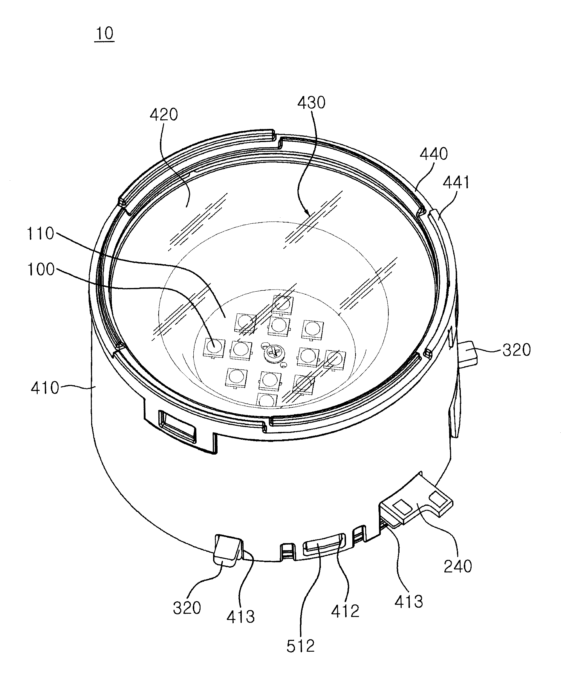
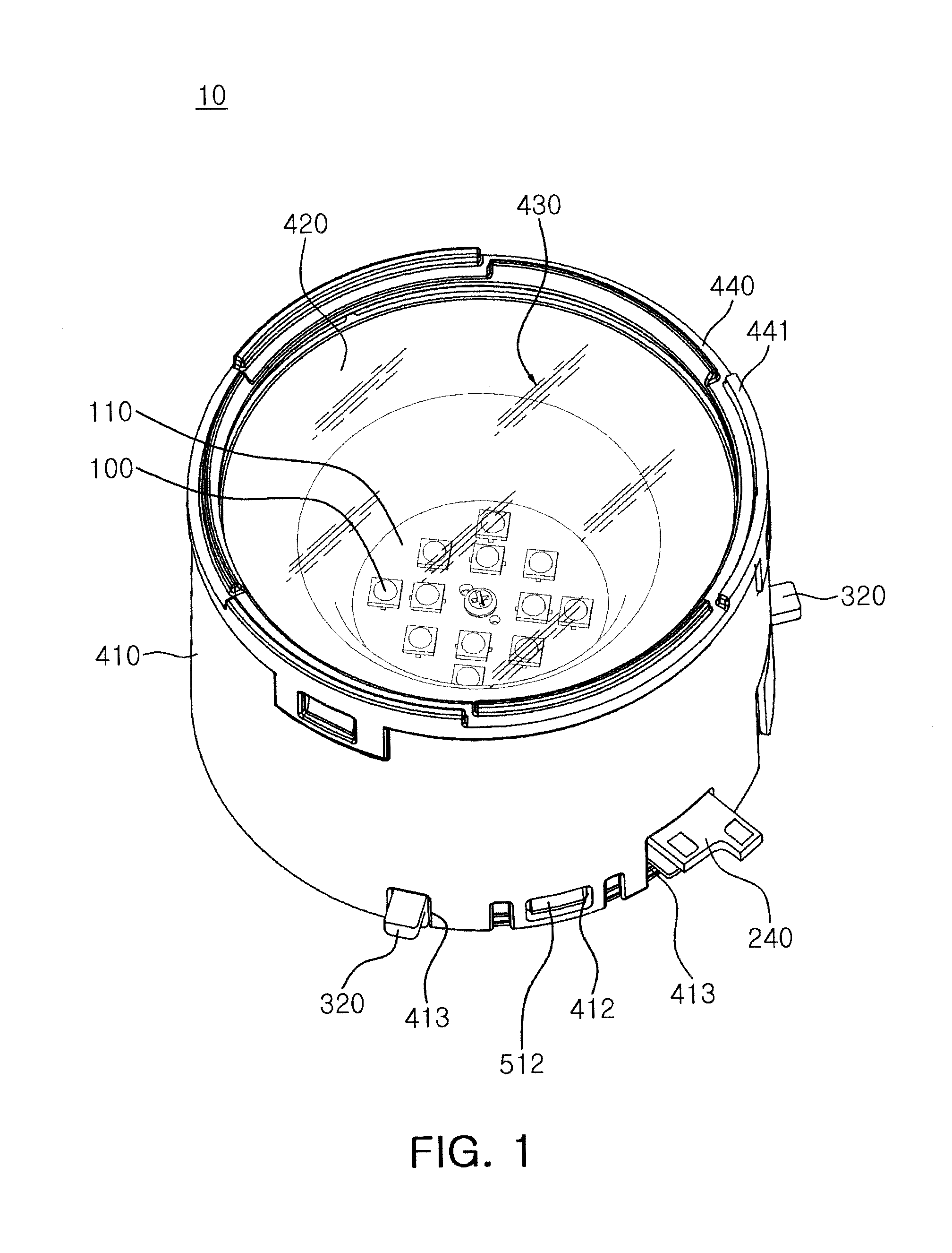
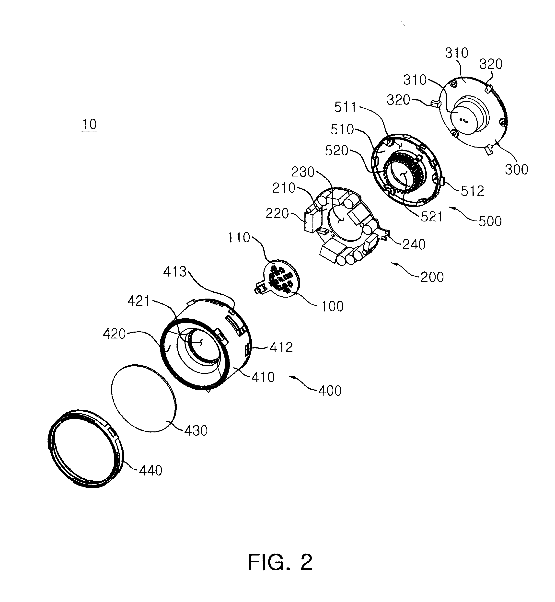
[0060]A light source for an illumination apparatus according to an embodiment of the invention will be described with reference to FIGS. 1 through 7.

[0061]As shown in FIGS. 1 and 2, a light source 10 for an illumination apparatus according to an embodiment of the invention includes a light emitting device 100, a power unit module 200, a support unit 300 and a housing un...


PUM

PropertyMeasurementUnit
angle of inclinationaaaaaaaaaa
angleaaaaaaaaaa
angleaaaaaaaaaa

Abstract

There is provided a light source for an illumination apparatus and a method of manufacturing the same. The light source includes a light emitting device; a power unit module supplying an electrical signal to the light emitting device; a support unit having the light emitting device thereon and discharging heat generated by the light emitting device to the outside; and a housing unit covering and protecting the light emitting device, the power unit module and the support unit. The light emitting device is disposed to have a height greater than that of a contact region between the power unit module and the housing unit with relation to a lower edge of the housing unit.

Description

CROSS-REFERENCE TO RELATED APPLICATIONS[0001]This application claims the priority of Korean Patent Application No. 10-2010-0123041 filed on Dec. 3, 2010, in the Korean Intellectual Property Office, the disclosure of which is incorporated herein by reference.BACKGROUND OF THE INVENTION[0002]1. Field of the Invention[0003]The present invention relates to a light source for an illumination apparatus and a method of manufacturing the same.[0004]2. Description of the Related Art[0005]A light emitting diode (LED) is a semiconductor device capable of emitting light of various colors through changes in compound semiconductor materials such as GaAs, AlGaAs, GaN, InGaP and the like when included in a light emitting source.[0006]Since LEDs have superior monochromic peak wavelengths and improved light emission efficiency as well as being miniaturizable, environmentally-friendly and low in power consumption, they are widely being used in various applications such as TVs, computers, illumination ...

Claims


Application Information

Patent Timeline
Patent Type & Authority Applications(United States)
IPC IPC(8): F21V33/00H05K3/00F21V29/00F21V15/01F21V7/00
CPCF21K9/30F21S2/005F21V7/04F21V7/09F21V15/01Y10T29/49124F21V23/006F21Y2101/02F21Y2105/001F21V29/70F21V19/006F21K9/20F21K9/68F21K9/69F21Y2105/10F21Y2115/10
Inventor WOO, YUN SEOKKOO, WON HOEBAE, JIN WOOJOUNG, WUK CHULBAEK, CHANG HOON
Owner SAMSUNG ELECTRONICS CO LTD
Learn More