Electron beam sterilizer

Active Publication Date: 2012-06-14
SHIBUYA IND CO LTD
View PDF5 Cites 23 Cited by
  • Summary
  • Abstract
  • Description
  • Claims
  • Application Information

AI Technical Summary

Benefits of technology

[0009]It is an object of the present invention to provide an electron beam sterilizer which prevents an article feeder from being adversely affecte

Problems solved by technology

If the electron beam is applied while the article feeder is not in operation, then the electron beam remains continuously applied to a localized area of the article feeder, tending to overheat and thermally deform the localized area.
Therefore, other tasks such as maintenance work on the article feeder cannot be performed during the process, making the electron beam sterilizer inefficient in its operation.
However, since ozone that is produced by the applied electron beam

Method used


Image

  • Electron beam sterilizer
  • Electron beam sterilizer
  • Electron beam sterilizer

Examples


first embodiment

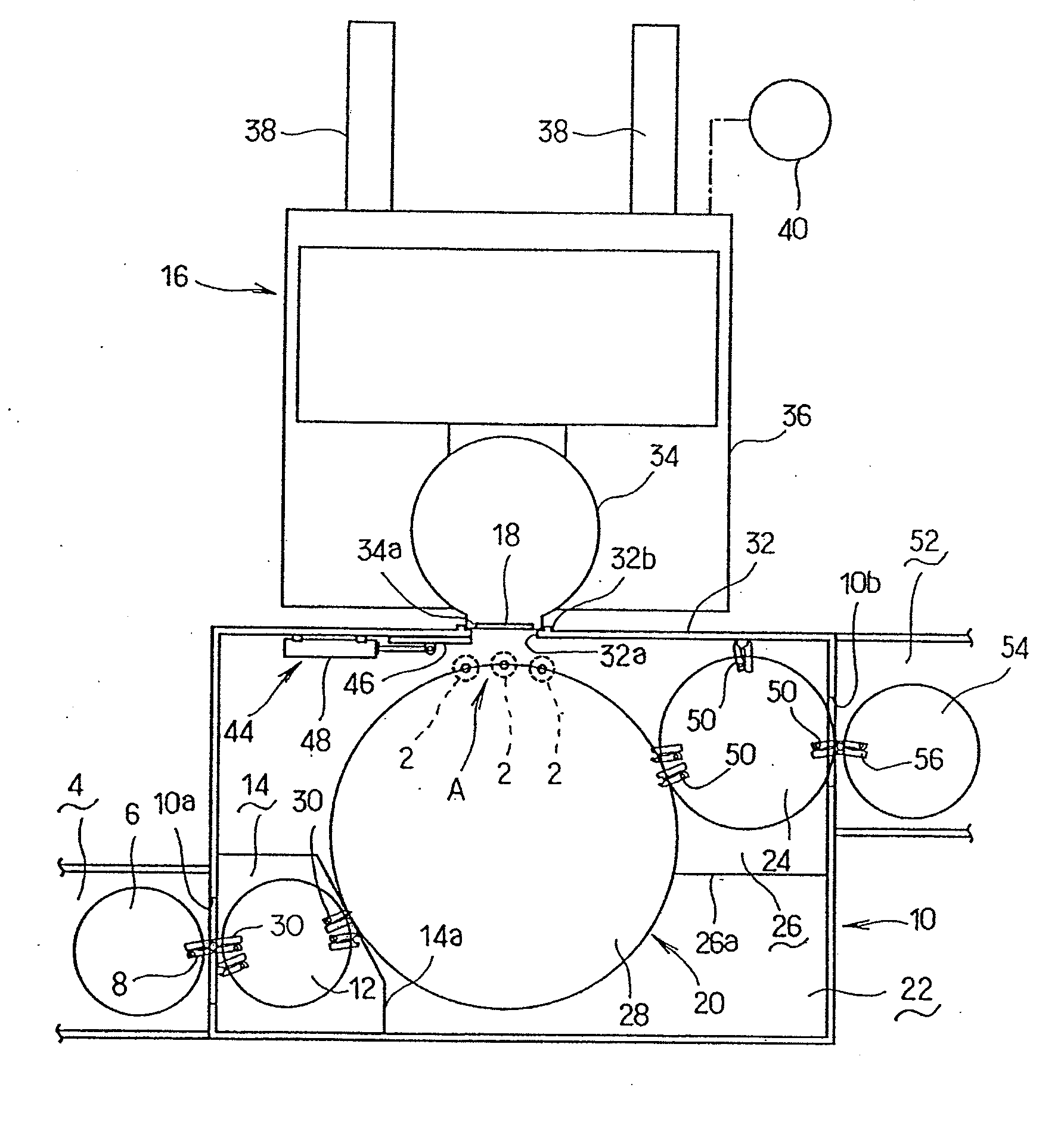
[0028]FIG. 1 is a plan view of an electron beam sterilizer according to a first embodiment of the present invention. As shown in FIG. 1, a container 2 which is irradiated and sterilized with an electron beam emitted from an electron beam sterilizer and which will subsequently be filled with contents such as a liquid is a plastic container such as a PET bottle or the like. The plastic container 2 has on its neck a flange supported at its lower surface by a support rail of an air feed conveyor, not shown. The plastic container 2 is fed along the air feed conveyor to the electron beam sterilizer by a jet of air applied to the rear side of the plastic container 2. When the plastic container 2 is fed to the electron beam sterilizer, the plastic container 2 is introduced into an introduction chamber 4 wherein the plastic container 2 is transferred to a loading wheel 6 disposed therein.

[0029]The loading wheel 6 in the introduction chamber 4 has a plurality of container grippers 8 as contai...

second embodiment

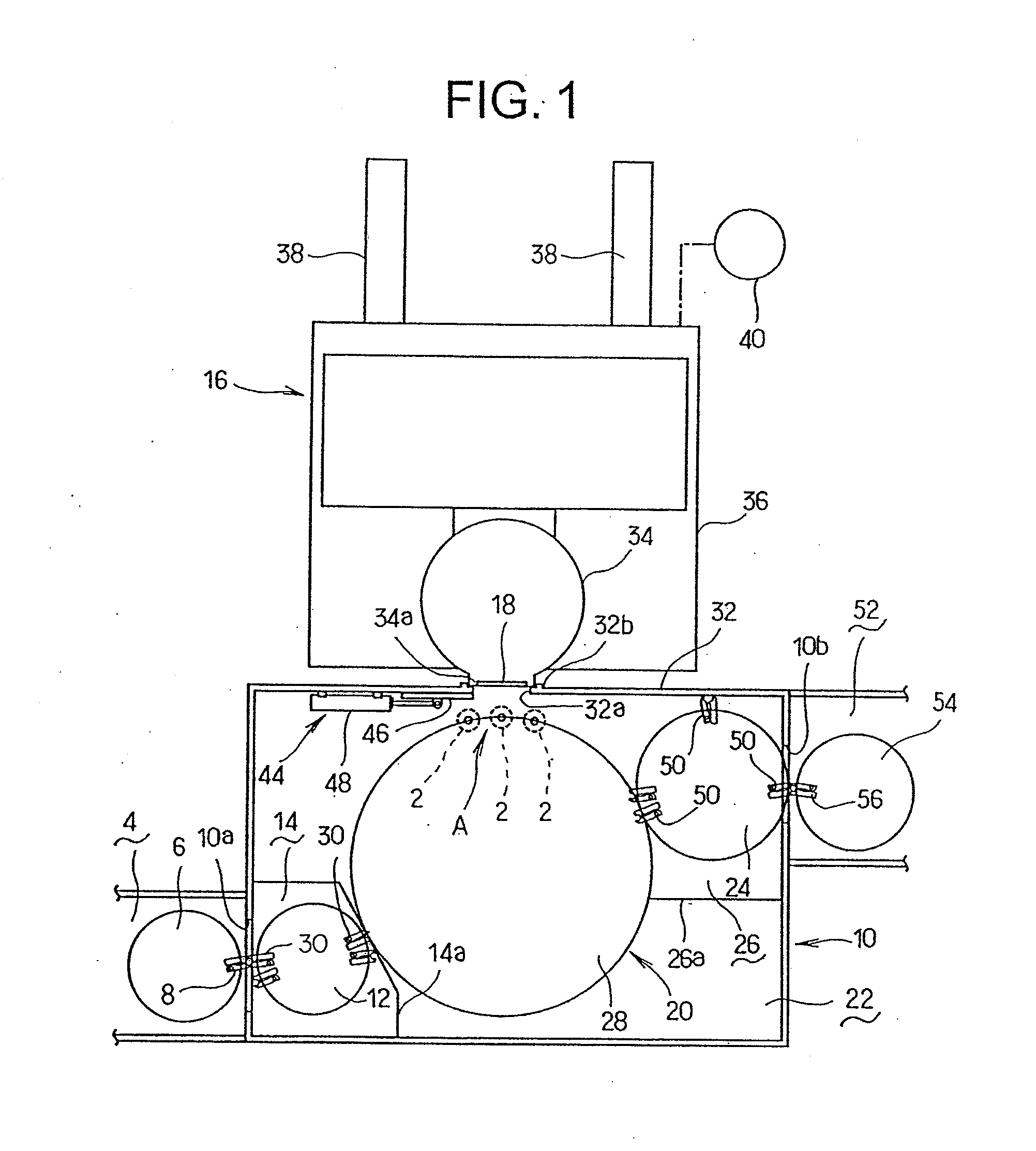
[0049]An electron beam sterilizer according to a second embodiment of the present invention will be described below with reference to FIG. 4. As shown in FIG. 4, the electron beam sterilizer according to the second embodiment includes an electron beam irradiation unit 34 and an adjustment irradiation box 60 coupled thereto, which are basically identical in structure to those of the electron beam sterilizer according to the first embodiment. The electron beam sterilizer according to the second embodiment resides in that it additionally includes a means for detecting whether the dose of an electron beam radiated from the electron beam irradiation unit 34 is normal or not. Those parts of the electron beam sterilizer according to the second embodiment which are identical to those of the electron beam sterilizer according to the first embodiment are denoted by identical reference characters, and will not be described in detail below, and only features unique to the second embodiment will...

third embodiment

[0051]FIGS. 5A and 5B show an adjustment radiation box 60 of an electron beam sterilizer according to a third embodiment of the present invention. According to the third embodiment, the adjustment radiation box 60 houses therein an electron beam receiver 100 with a number of small separate dose films 102 mounted on its entire front surface which faces the irradiation window 18. The dose films 102 are manually installed on and removed from the electron beam receiver 100. In operation, the electron beam receiver 100 with the dose films 102 mounted on its entire front surface is placed in the adjustment radiation box 60, and the adjustment radiation box 60 is coupled to the electron beam irradiation unit 34. Then, the electron beam receiver 100 is irradiated with an electron beam radiated from the electron beam irradiation unit 34.

[0052]After the electron beam receiver 100 is irradiated with the electron beam, the dose films 102 are removed one by one from the electron beam receiver 10...


PUM


Abstract

Plastic containers fed by an article feeder housed in a shield chamber sterilized by being irradiated with an electron beam that is radiated from an irradiation window of an electron beam irradiation unit which is coupled to an opening of the shield chamber. In a maintenance mode, an adjustment irradiation box is detachably mounted on the electron beam irradiation unit in covering relation to the irradiation window of the electron beam irradiation unit. The adjustment irradiation box houses therein an electron beam receiver for receiving the electron beam radiated from the irradiation window, a cooling mechanism for cooling the electron beam receiver, and an exhaust mechanism for discharging an atmosphere in the adjustment irradiation box.

Description

BACKGROUND OF THE INVENTION[0001]1. Field of the Invention[0002]The present invention relates to an electron beam sterilizer for irradiating an article that is being fed by a feeder with an electron beam to sterilize the article, and more particularly to an arrangement for carrying out maintenance work on an electron beam irradiation unit for radiating an electron beam.[0003]2. Description of the Related Art[0004]Electron beam sterilizers generally include an article feeder for successively feeding articles into an isolated sterilization chamber and an electron beam irradiation unit having an irradiation window positioned in facing relation to an opening in the sterilization chamber, thereby coupling the sterilization chamber and the electron beam irradiation unit to each other. Articles that are fed into sterilization chamber by the article feeder are sterilized by an electron beam that is applied from the electron beam irradiation unit through the irradiation window to the article...

Claims


Application Information

Patent Timeline
IPC IPC(8): A61L2/08
CPCA61L2/087A61L2202/121G21K5/10G21K5/04A61L2202/122
Inventor NISHINO, YUKINOBUNISHI, TOKUOYAMAMOTO, YUKIHIRO
Owner SHIBUYA IND CO LTD
Why Eureka
Try Eureka