
Projection display apparauts which enables a selected image inverting process to be performed to facilitate registration adjustment

a technology of projection display and inverting process, which is applied in the direction of television systems, instruments, pulse techniques, etc., can solve the problems of difficulty for users to perform registration adjustments, and achieve the effects of reducing horizontal and/or vertical misregistration, easy operation of inputting the correction value by users, and improved display quality

Active Publication Date: 2012-06-14
SONY GRP CORP
View PDF3 Cites 3 Cited by
  • Summary
  • Abstract
  • Description
  • Claims
  • Application Information

AI Technical Summary

Benefits of technology

This solution improves display quality by reducing misregistration between primary color lights and simplifies the registration adjustment process for users, ensuring proper image inversion and alignment irrespective of the apparatus's usage situation.

Problems solved by technology

An issue arises such that it is difficult for the user to perform the registration adjustment.

Method used


Image

  • Projection display apparauts which enables a selected image inverting process to be performed to facilitate registration adjustment
  • Projection display apparauts which enables a selected image inverting process to be performed to facilitate registration adjustment
  • Projection display apparauts which enables a selected image inverting process to be performed to facilitate registration adjustment

Examples


Embodiment Construction

[0034]An embodiment of the present invention will be described in detail hereinbelow with reference to the drawings.

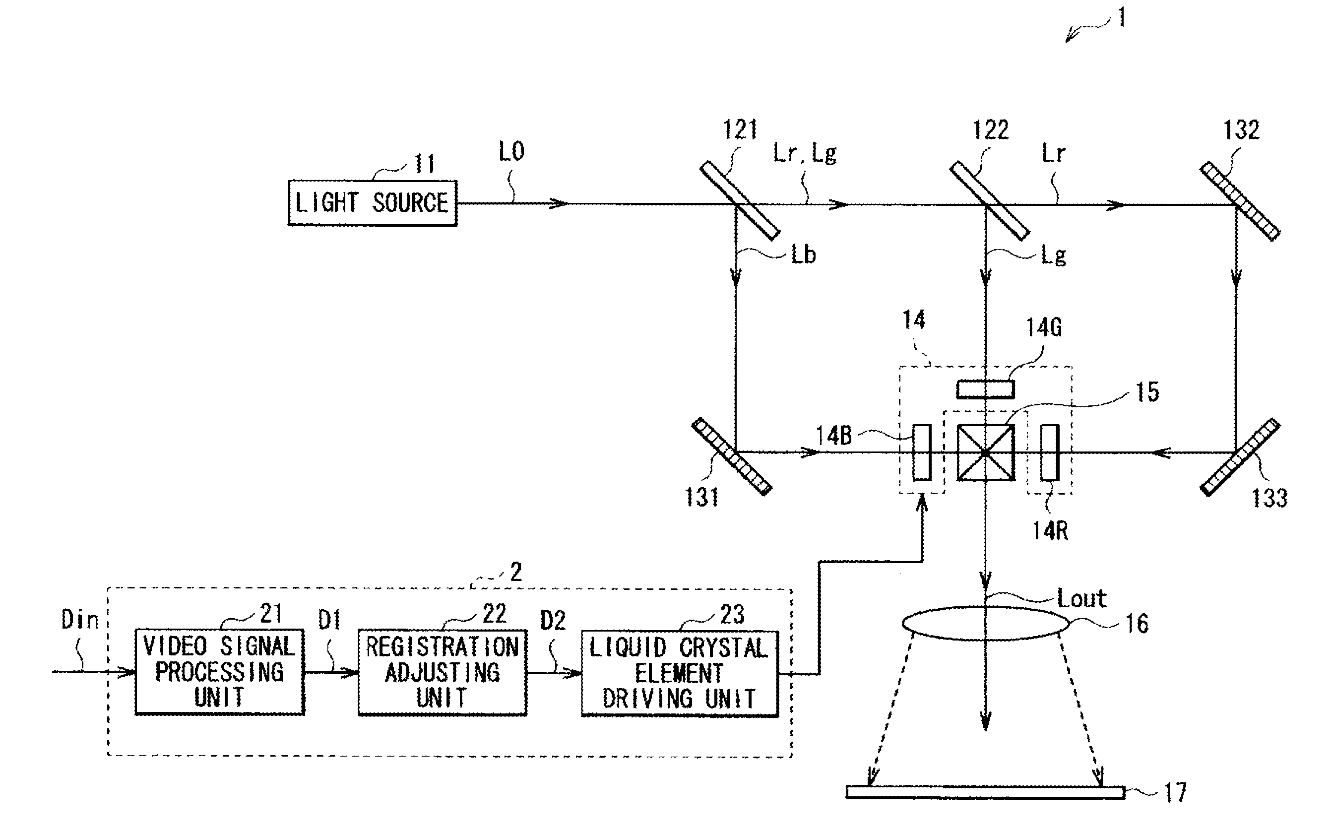
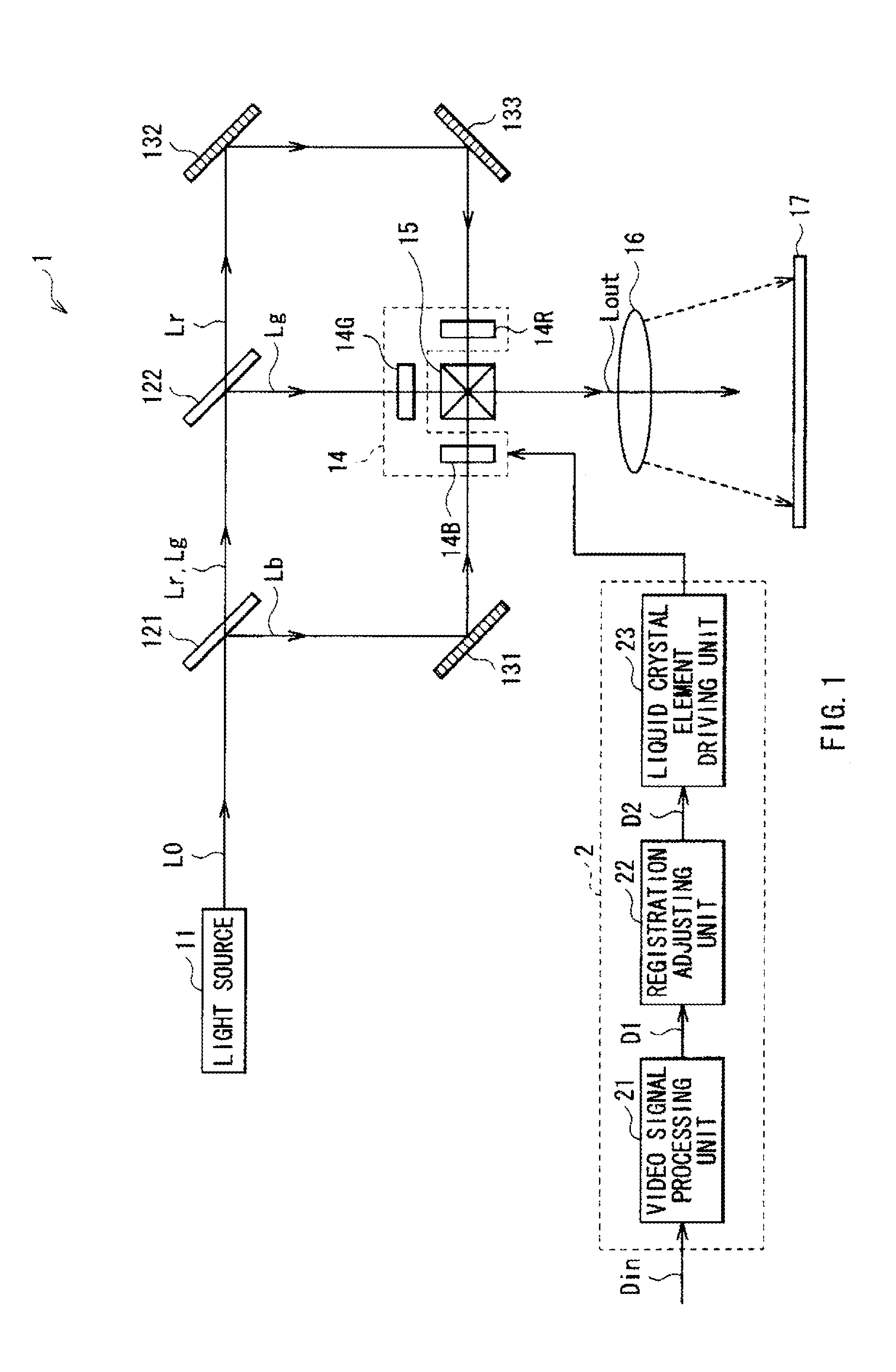
[0035]FIG. 1 shows a general configuration of a projection display apparatus (liquid crystal projector 1) as an embodiment of the present invention. The liquid crystal projector 1 displays a video image on the basis of an input video signal Din supplied from the outside. The liquid crystal projector 1 includes a light source 11, dichroic mirrors 121 and 122, reflection mirrors 131, 132, and 133, a light modulator 14, a dichroic prism 15, a projection lens 16, a screen 17, and a control unit 2 for controlling the light modulator 14 on the basis of the input video signal Din.

[0036]The light source 11 generates white light including primary color light of red light (R), blue light (B), and green light (G) which is necessary to display a color image. The light source 11 is configured by, for example, a halogen lamp, a metal halide lamp, a xenon lamp, or the like.

[0037]The ...


PUM


Abstract

The present invention provides a projection display apparatus realizing improved operability at the time of registration adjustment irrespective of a use situation of the apparatus. In the case where misregistration occurs between primary color lights, video signals for three colors are corrected (registration adjustment is performed) so as to reduce the misregistration in accordance with an input adjustment value. An image inverting process is performed on an input video signal so that the image is inverted in a display screen. By a configuration by the user, the image is properly inverted in the display screen. When the image inverting process is performed, an adjustment value, with a sign different from that in the misregistration direction in a coordinate system where the image is not inverted, is input by an operation on the display screen.

Description

CROSS-REFERENCE TO RELATED APPLICATIONS[0001]The present application is a continuation, of U.S. patent application Ser. No. 12 / 220,299, filed Jul. 23, 2008, which claims priority from Japanese Patent Application No. JP 2007-193789, filed in the Japanese Patent Office on Jul. 25, 2007, the disclosure of which is hereby incorporated herein by reference.BACKGROUND OF THE INVENTION[0002]1. Field of the Invention[0003]The present invention relates to a projection display apparatus applied to a liquid crystal projector and the like.[0004]2. Description of the Related Art[0005]A projection display apparatus (for example, a liquid crystal projector) is being spread, which displays a picture by spatially modulating incident light on a spatial light modulation device in accordance with an electric signal applied to the spatial light modulation device, outputting the modulated light, and collecting and projecting the outgoing light. Such a projection display apparatus has generally a lamp as a...

Claims


Application Information

Patent Timeline
Patent Type & Authority Applications(United States)
IPC IPC(8): H04N9/31
CPCH04N9/312H04N9/3197H04N9/3185H04N5/74
Inventor NISHIMURA, KOICHIROKONDO, YOSHITAKE
Owner SONY GRP CORP
Learn More