

Light source unit and projector
a technology of light source unit and projector, which is applied in the direction of instruments, lighting and heating apparatus, optical elements, etc., can solve the problem that the angle at which the substrate is coated with luminescent materials cannot be changed to arbitrary angles during the operation
- Summary
- Abstract
- Description
- Claims
- Application Information
AI Technical Summary
Benefits of technology
Problems solved by technology
Method used
Image

Examples
first embodiment
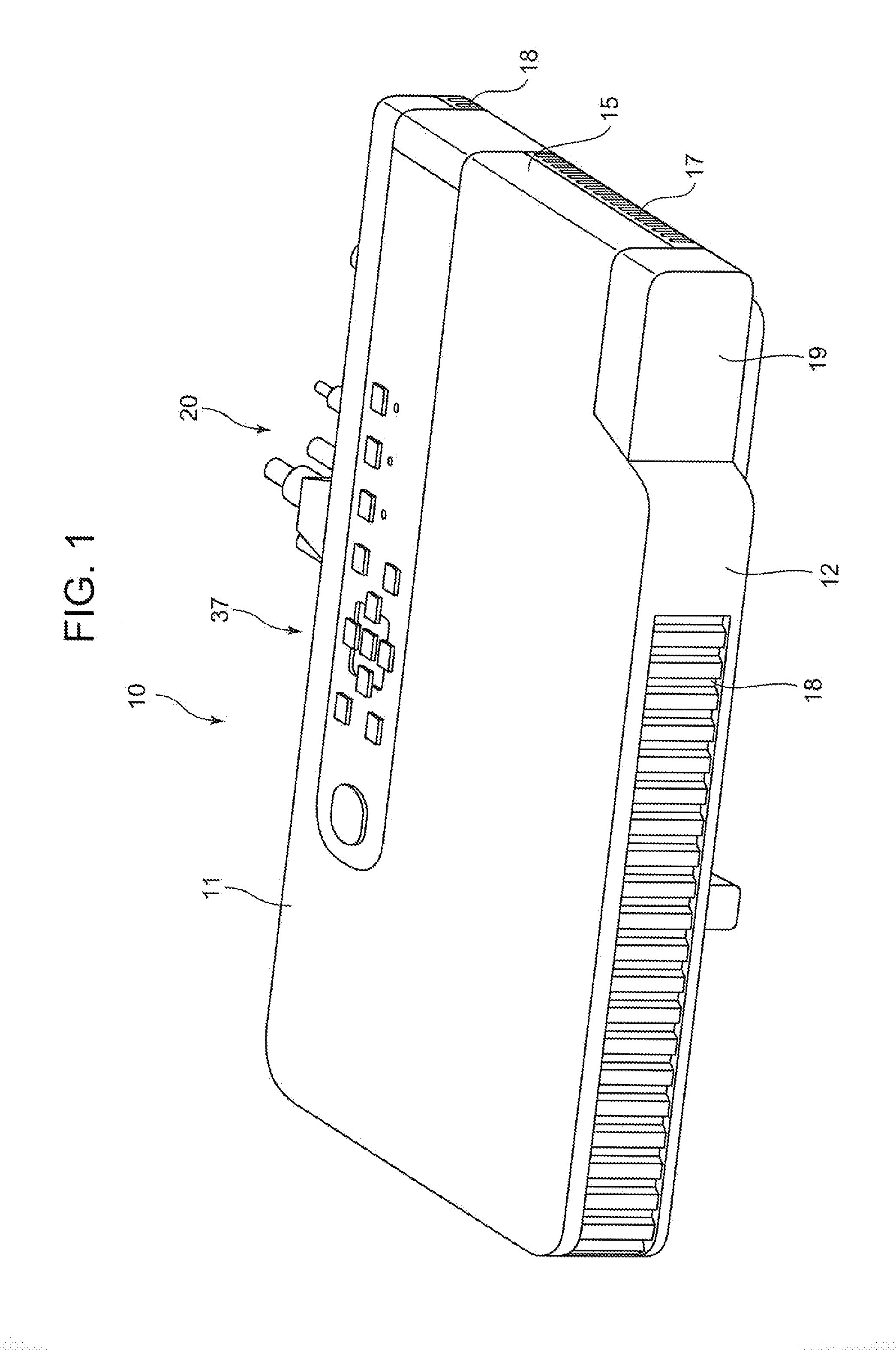
[0038]Hereinafter, a first embodiment of the invention will be described. FIG. 1 is a perspective view showing an external appearance of a projector 10. In this embodiment, left and right with respect to the projector 10 denote, respectively, left and right directions with respect to a projecting direction, and front and rear denote, respectively, front and rear directions with respect to a direction towards a screen and a traveling direction of a pencil of light.
[0039]As is shown in FIG. 1, the projector 10 has a substantially rectangular parallelepiped shape and has a lens cover 19 which covers a projection port which is laid to a side of a front panel 12 which is referred to as a front side panel of a projector casing, as well as a plurality of outside air inlet ports 18 which are formed in the front panel 12. Further, although not shown, the projector 10 includes an Ir reception unit which receives a control signal from a remote controller.
[0040]In addition, a keys / indicators un...
second embodiment
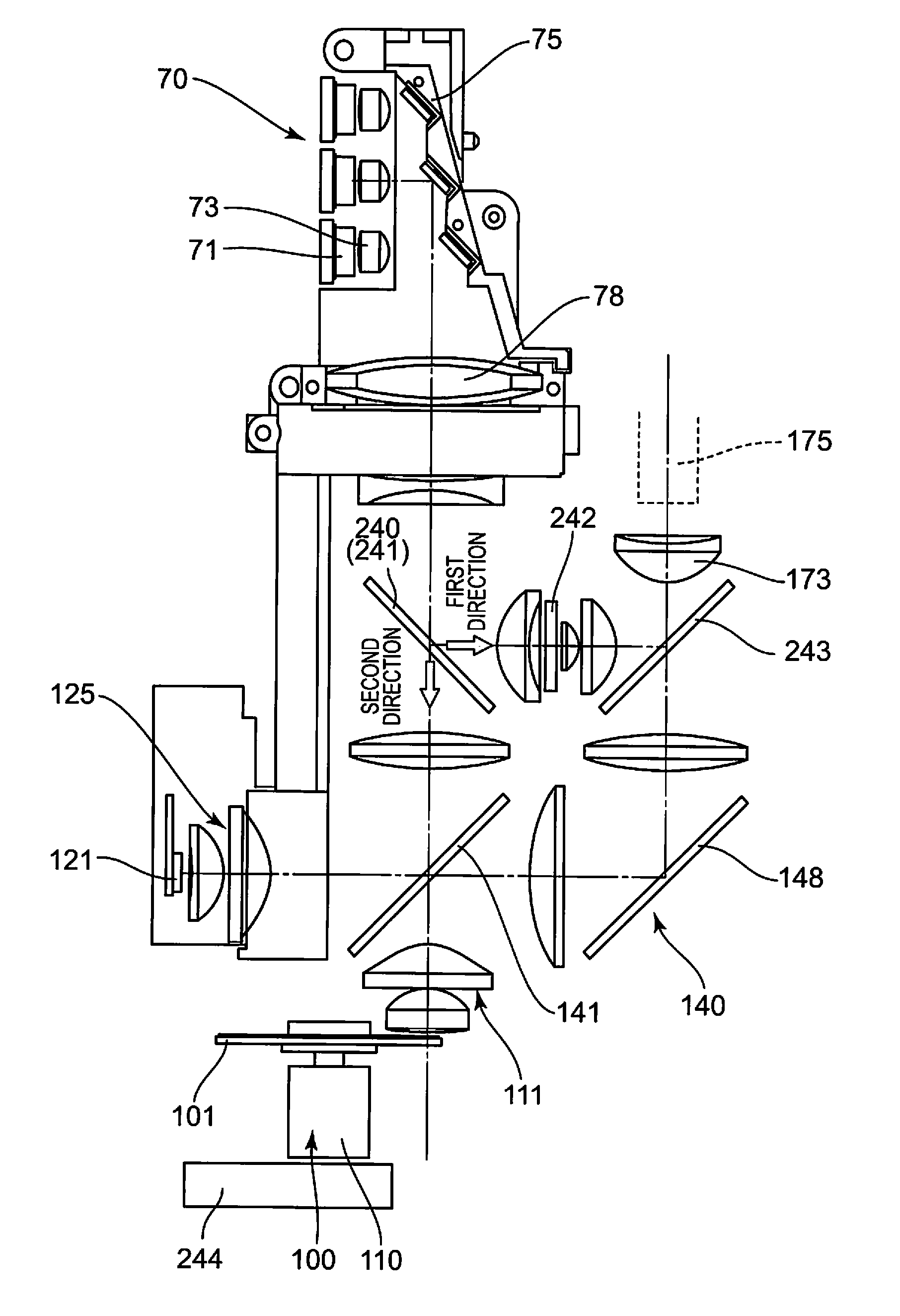
[0085]The invention is not limited to the use of a red light emitting diode for a red light source 121 which is a second light source. As FIG. 6 shows, red laser emitting devices 255 can also be used as a red light source.
[0086]In the case of red laser emitting devices 255 being used as a red light source 121, like the blue laser light emitting devices of the excitation light shining device 70, the red laser emitting devices 255 are a total of six semiconductor light emitting elements which are arranged into a matrix of two rows and three columns. Collimator lenses 256 are disposed individually on optical axes of the red laser emitting devices 255 as is shown in the FIG. 6. The collimator lenses 256 are collective lenses which convert light emitted from the red laser emitting devices 255 into parallel light. In addition, a group of reflection mirrors 257 is made up of a plurality of reflection mirrors which are arranged in a step-like fashion. The reflection mirrors 257 reduce in on...
third embodiment
Modified Example of Third Embodiment
[0107]Any other member than the magnetic optical element 252 can be used as the polarization changing device 250. For example, a switching polarization rotary element 253 can be used as a polarization changing device 250. This switching polarization rotary element 253 is made up of a liquid crystal switching element and changes the plane of polarization of light when energized.
[0108]The switching polarization rotary element 253 is a liquid crystal switching element which selectively rotates the plane of polarization of incident light for emission. This switching polarization rotary element 253 is an element which switches states of excitation light between two states which are indicated black and white, respectively, when representing them on a liquid crystal display.
[0109]In general, the switching polarization rotary element 253 performs two functions to rotate and not to rotate the plane of polarization of P-polarized light which passes therethr...
PUM
 Abstract
Description
Claims
Application Information