Circuit and method for regulating a DC voltage and power converter

a dc voltage and power converter technology, applied in the direction of electric generator control, process and machine control, instruments, etc., can solve the problems of overvoltage of dc-links, increased overall cost of power converters, and large capacitance values, so as to achieve high integrity voltage clamp systems and increase the effect of capacitan

Active Publication Date: 2012-06-14
SIEMENS AG
View PDF7 Cites 15 Cited by
  • Summary
  • Abstract
  • Description
  • Claims
  • Application Information

AI Technical Summary

Benefits of technology

[0017]The second DC voltage threshold (above which the second control signal is generated to satisfy the second criterion or e.g. to be above the second threshold) is greater (such as by at least 100 V or 200 V) than the first DC voltage threshold (above which the first control signal is generated to satisfy the first criterion or e.g. to be above the first threshold). Thus, when the DC voltage raises above the first DC voltage threshold, the first control circuit will generate the first control signal to satisfy the first criterion or e.g. to be above the first threshold such that the controllable switch system establishes an electrical connection between the first terminal and the second terminal. However, the establishment of the electrical connection may fail. In this case, the DC voltage may rise still further to reach the second DC voltage threshold. In this case the second control circuit (acting as a fallback circuit in case the first control circuit fails or in case the controllable switch system does not properly function with respect to the first control terminal) will generate the second control signal to satisfy the second criterion or e.g. to be above the second threshold such that the controllable switch system establishes an electrical connection between the first terminal and the second terminal. Thereby, an overvoltage may be reduced for preventing damage to electrical or electronic components of circuitry connected between the first DC voltage terminal and the second DC voltage terminal. Thereby, the second control circuit may act as an emergency circuit, when the function of the controllable switch system being controlled exclusively by the first control circuit fails.
[0018]In particular, with the present embodiment the MP capacitors may be integrated into the power converter without having to increase their capacitance and hence cost to deal with the ultimate voltage limiting function through passive means. Typical operational voltage levels for the IGBT switch associated with the voltage clamp switch may be 1100 V for an IGBT device with a non-switching (VCE sustaining) rating of 1700 V.
[0019]In a conventional system, under a fault condition of the direct drive generator (for example of a wind turbine) with a massive electrolytic capacitor bank, the bank is dimensioned such that the ultimate overvoltage is less than 1700 V which is the limiting voltage for the IGBT device in this example. According to an embodiment the MP capacitor in the system may be dimensioned for all requirements except the ultimate overvoltage surge requirement. Thus, according to an embodiment a MP capacitor bank of say 25% of the capacitance of the electrolytic bank may be required. According to an embodiment the operation of the voltage clamp (also referred to as circuit for regulating a DC voltage) of the present embodiment may be ensured, in order to protect the further electronic components from an overvoltage. Thus, a high integrity voltage clamp system is provided.

Problems solved by technology

For example, a permanent magnet generator may release a current (in particular during shutdown) which may result in an overvoltage of the DC-link.
The disadvantage of MP capacitors however is that for the same capacitance value they are much larger and have a much higher cost.
Thereby, the overall cost of the power converter may increase.

Method used


Image

  • Circuit and method for regulating a DC voltage and power converter
  • Circuit and method for regulating a DC voltage and power converter
  • Circuit and method for regulating a DC voltage and power converter

Examples


Embodiment Construction

[0051]The illustration in the drawing is shown in schematic form. It is noted that in different figures, similar or identical elements are provided with the same reference signs or with reference signs, which are different from the corresponding reference signs only within the first digit.

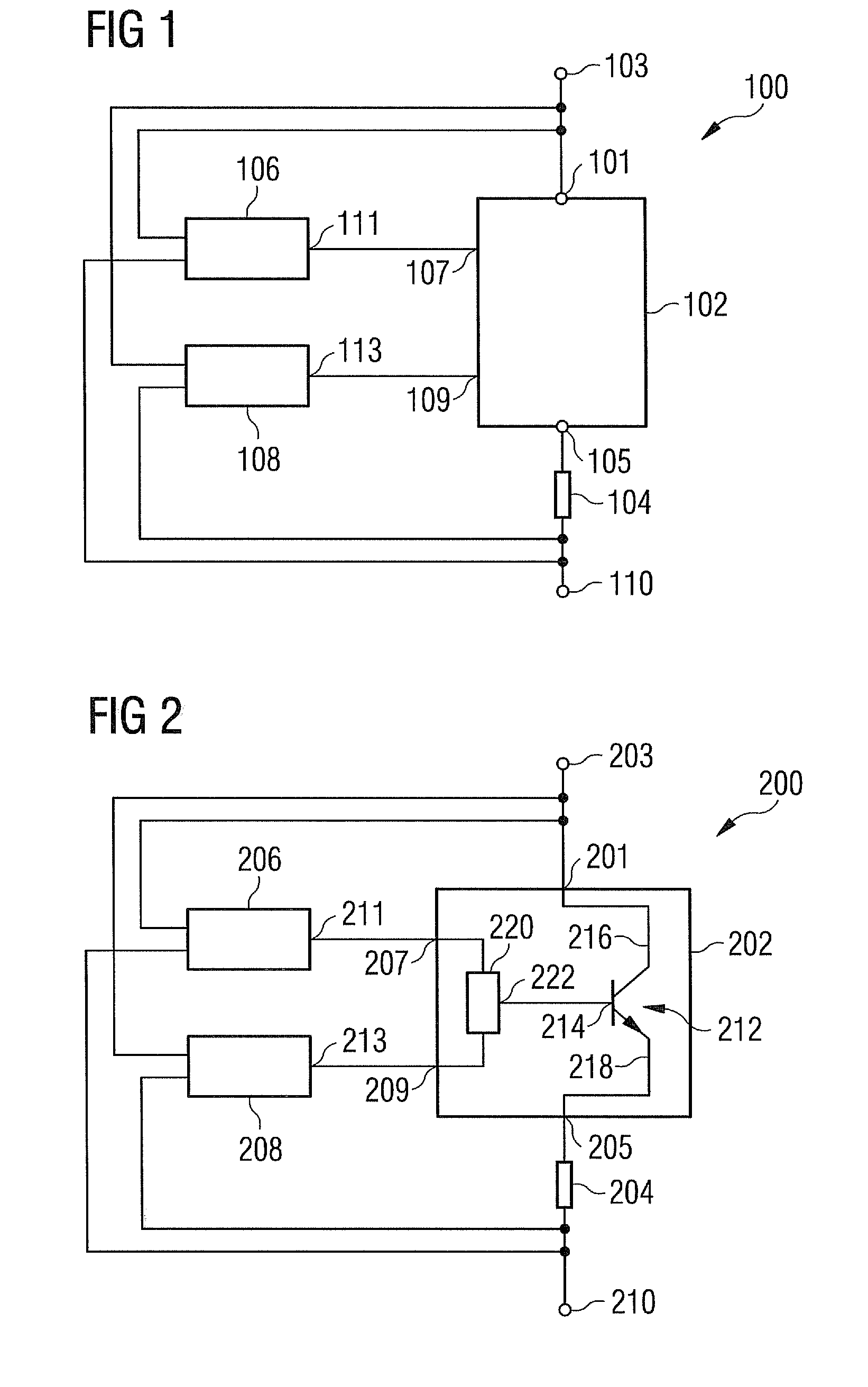
[0052]FIG. 1 schematically illustrates a block diagram of a circuit 100 for regulating a DC voltage according to an embodiment. The circuit 100 comprises a controllable switch system 102, a resistor 104, a first control circuit 106 and a second control circuit 108. The controllable switch system 102 has a first terminal 101 connectable to the first DC voltage terminal 103, a second terminal 105, a first control terminal 107, and a second control terminal 109. The first control circuit 106 generates a first control signal at a first control output terminal 111 and the second control circuit generates a second control signal at a second control output terminal 113. The controllable switch system esta...


PUM


Abstract

A circuit for regulating a DC voltage is provided. The circuit includes: a controllable switch system, a resistor, a first control circuit and a second control circuit. The controllable switch system includes a first terminal, a second terminal, a first control terminal, and a second control terminal. The controllable switch system is configured to establish an electrical connection between the first terminal and the second terminal, if a first control signal applied to the first control terminal satisfies a first criterion or if a second control signal applied to the second control terminal satisfies a second criterion; A A method for regulating a DC voltage and an AC-to-AC-converter are described.

Description

CROSS REFERENCE TO RELATED APPLICATIONS[0001]This application claims priority of European Patent Office application No. 10194148.2 EP filed Dec. 8, 2010, which is incorporated by reference herein in its entirety.FIELD OF INVENTION[0002]The present invention relates to a circuit and to a method for regulating a DC voltage applied between a first DC voltage terminal and a second DC voltage terminal. Further, the present invention relates to an AC-to-AC converter for converting a first frequency AC-voltage to a second frequency AC-voltage, wherein the converter comprises the circuit for regulating a DC voltage.ART BACKGROUND[0003]In a conventional AC-to-AC converter (in particular converting a variable frequency AC voltage to a fixed frequency AC voltage) a first section may convert an AC-voltage (or current or power) to a DC-voltage (or current or power) generated at a so-called DC-link. A second section of the converter may convert the DC-voltage at the DC-link to a (in particular fi...

Claims


Application Information

Patent Timeline
Patent Type & Authority Applications(United States)
IPC IPC(8): H02M5/458G05F1/46
CPCH02M1/32H02P9/105H02M2001/322H02M5/458H02H7/1216H02H9/005H02H9/041H02H9/042H02M1/322
Inventor JONES, RODNEY
Owner SIEMENS AG
Why Eureka
Try Eureka