Methods, Systems, and Software for Controlling a Power Converter During Low (Zero)-Voltage Ride-Through Conditions

a technology of low (zero) voltage and power converter, applied in the field of power electronics, can solve problems such as deep dips and sags, types of faults commonly occurring, and significant voltage drop for a short duration

Inactive Publication Date: 2012-06-14
NORTHERN POWER SYST UTILITY SCALE
View PDF3 Cites 33 Cited by
  • Summary
  • Abstract
  • Description
  • Claims
  • Application Information

AI Technical Summary

Benefits of technology

[0008]In another implementation, the present disclosure is directed to an apparatus for controlling the AC output of a power converter connected to an AC power network subject to a voltage fault that causes a network voltage on the AC power network to drop below a normal operating level during a fault period. The apparatus includes a control system designed and configured to: estimate the phase angle of the voltage anticipated to be present on the AC power network when the network voltage recovers from the voltage fault; and control a current of the AC output during the voltage fault as a function of the phase angle estimated.

Problems solved by technology

Occasionally, a disturbance occurs on a utility system, or other power network, that results in a significant voltage drop for a short duration (typically less than 500 ms).
Faults can be caused, for example, by a single phase conductor being inadvertently connected to ground or the inadvertent connection or short circuiting of multiple phase conductors.
These types of faults commonly occur due to equipment failure, bad weather, a vehicular accident, etc.
Closer faults cause deeper dips and sags.
Problems such as frequency swings or large system-wide instabilities of power-generating systems can lead to the disruption of power to large regions, affecting large numbers of power customers.

Method used


Image

  • Methods, Systems, and Software for Controlling a Power Converter During Low (Zero)-Voltage Ride-Through Conditions
  • Methods, Systems, and Software for Controlling a Power Converter During Low (Zero)-Voltage Ride-Through Conditions
  • Methods, Systems, and Software for Controlling a Power Converter During Low (Zero)-Voltage Ride-Through Conditions

Examples


Embodiment Construction

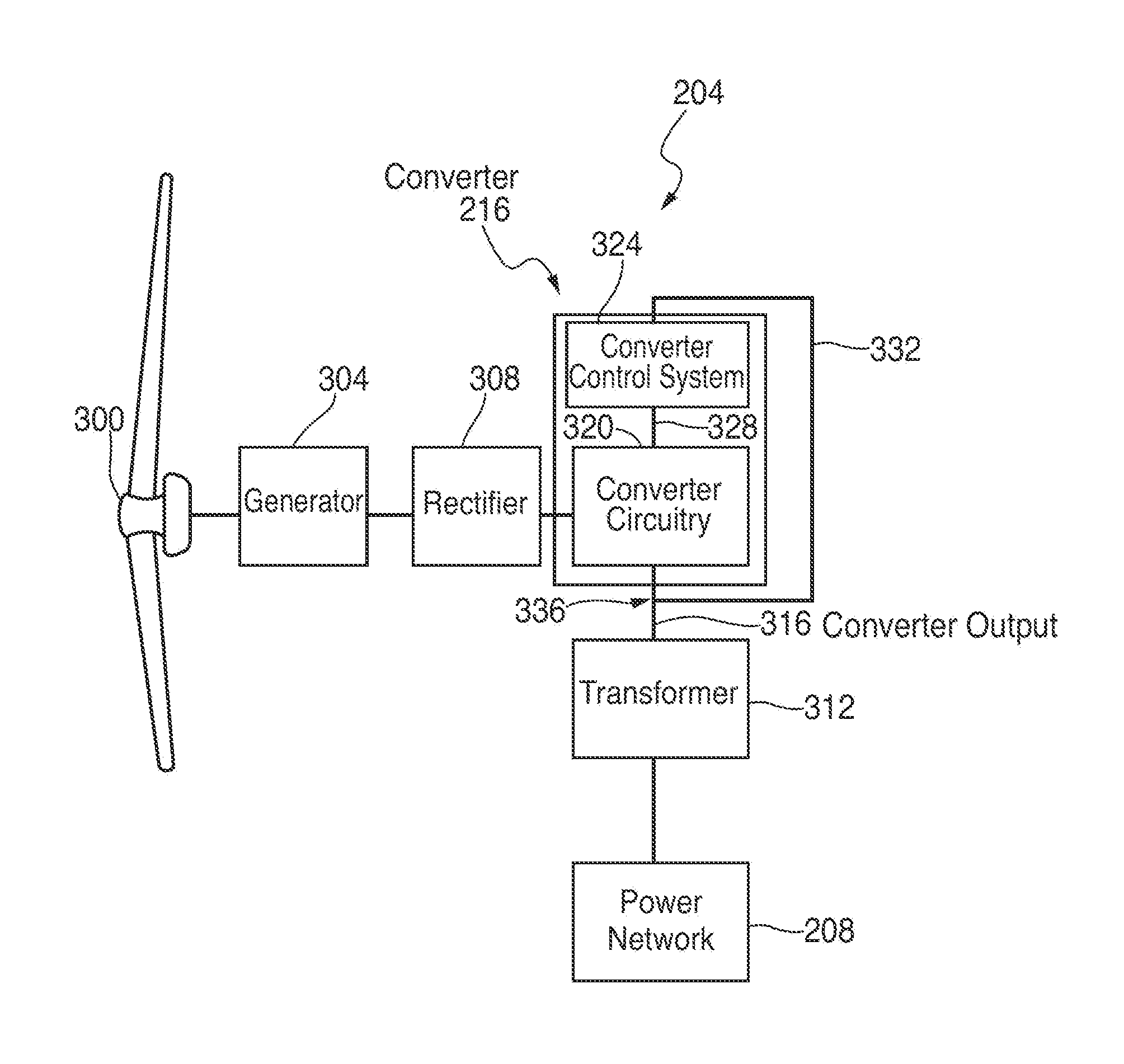
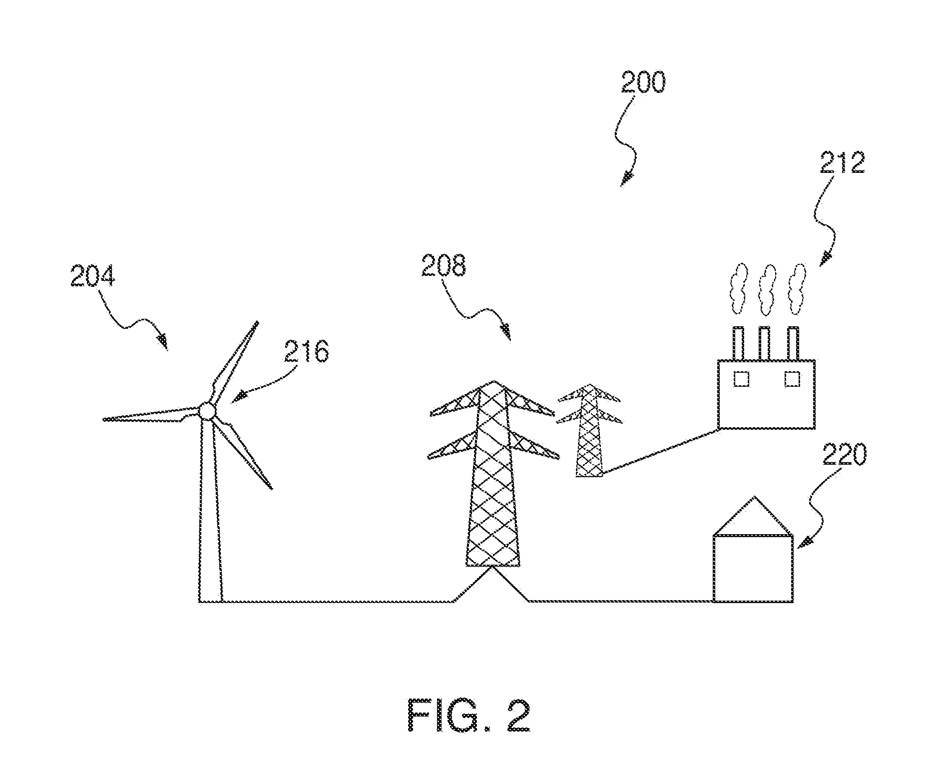
[0018]Referring now to FIG. 2, this figure illustrates an exemplary alternating current (AC) power system 200 that includes a wind power unit (WPU) 204 that delivers electrical energy to a power network 208, which is also supplied power by one or more additional power sources, such as a coal fired power plant 212. A power converter 216 is coupled between WPU 204 and power network 208 for controlling electrical characteristics of the power delivered by the WPU to the network and that is ultimately delivered to end users, for example, utility customers, collectively represented in FIG. 2 by element 220. As described below in detail, power converter 216 provides ride-through capabilities for WPU 204 during certain events that result in low voltage and / or zero voltage on power network 208. In other words, power converter 216 is designed and configured to allow WPU 204 to remain connected, and continue supplying power, to power network 208 during such events. In this manner, power conver...


PUM


Abstract

A power converter control system having a phase tracker that is designed and configured to estimate the phase of the voltage on the power network that will be on the network when network recovers from a fault on the network. Such a power converter control system allows a power-network-connected power source to ride-through a fault event and continue supplying power thereto at the designed phase and frequency. In one embodiment, the phase tracker provides this estimate by having a response time slow enough that the voltage drop or sag caused by the fault substantially does not affect the control system. In another embodiment, the phase detector is designed and configured to freeze the frequency of its output upon detection of a fault event on the power network.

Description

RELATED APPLICATION DATA[0001]This application claims the benefit of priority of U.S. Provisional Application Ser. No. 61 / 422,451, filed on Dec. 13, 2010, and titled “Method And System For Controlling A Power Converter During Voltage Faults And Surges” and U.S. Provisional Application Ser. No. 61 / 425,510, filed on Dec. 21, 2010, and titled “Inverter Control For Fast Voltage Mitigation And Zero Voltage Ride-Through,” both of which are incorporated by reference herein in their entireties.FIELD OF THE INVENTION[0002]The present invention generally relates to the field of power electronics. In particular, the present invention is directed to methods, systems, and software for controlling a power converter during low(zero)-voltage ride-through conditions.BACKGROUND[0003]Occasionally, a disturbance occurs on a utility system, or other power network, that results in a significant voltage drop for a short duration (typically less than 500 ms). Such a disturbance is generally caused by a fau...

Claims


Application Information

Patent Timeline
Patent Type & Authority Applications(United States)
IPC IPC(8): H02M7/5383
CPCF03D9/003F05B2270/10711H02J3/24H02H7/122H02P9/105Y02E10/72Y02E10/763H02J3/40F03D9/255Y02E10/76
Inventor PETTER, JEFFREY K.
Owner NORTHERN POWER SYST UTILITY SCALE
Why Eureka
Try Eureka