Linear Bearing Assembly and Method

a technology of linear bearings and bearings, applied in the direction of sliding contact bearings, rigid support of bearings, mechanical apparatus, etc., can solve the problems of permanent deformation (denting) of the race surface, bearing damage, and small distance between objects, so as to prevent lubrication starvation and localized race wear, reduce static friction or “stiction”, and reduce lubrication starvation or ball/roller skidding during motion

Inactive Publication Date: 2012-06-14
AB SKF
View PDF6 Cites 7 Cited by
  • Summary
  • Abstract
  • Description
  • Claims
  • Application Information

AI Technical Summary

Benefits of technology

[0017]An advantage of the present invention is to provide a system and method to reduce the static friction or “stiction” in a linear or roller bearings.
[0018]Another advantage of the present invention is to provide a system and method can also be used with small amplitude reciprocating motions to prevent lubrication starvation and localized race wear in different bearing applications.
[0019]Still another advantage of the present invention is to provide a system and method to alter bearing element accelerations ther

Problems solved by technology

This jumping action prevents the smooth acceleration of the object from other components operably connected with one another thereby presenting problems for moving the object a small distance as it tends to jump past the intended stopping point.
In the linear bearing systems that are heavily loaded but remain stationary for long periods of time, there is the possibility of the bearings being damaged by “false brinelling”, a condition where the load on a stationary rolling element is large enough to cause the element, over time, to permanently deform (dent) the race surface.
As appreciated by those skilled in metal arts, “false brinelling” is damage caused by fretting, which causes imprints.
These imprints look similar to “brinelling” thereby resulting in permanent material deformation.
Without the lubricant, wear is increased and the resulting wear debris may oxidize and form an abrasive compound, which further accelerates wear.
While bearings and races appear smooth to the eye, they are microscopically rough.
One method of preventing “false brinelling” is to move the object, or rotate the shaft, periodically, which is inconvenient or even impossible in certain application thereby resulting in total replacement of the bearing assembly.
If t

Method used


Image

  • Linear Bearing Assembly and Method
  • Linear Bearing Assembly and Method
  • Linear Bearing Assembly and Method

Examples


Embodiment Construction

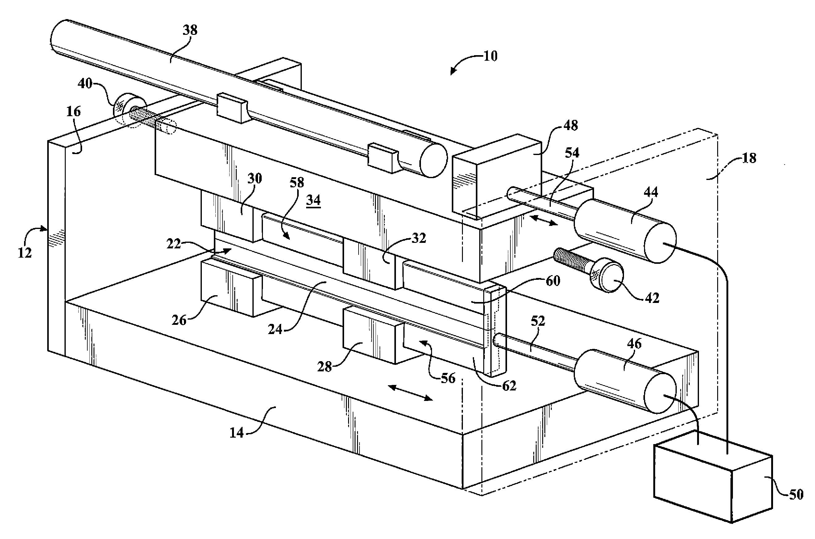
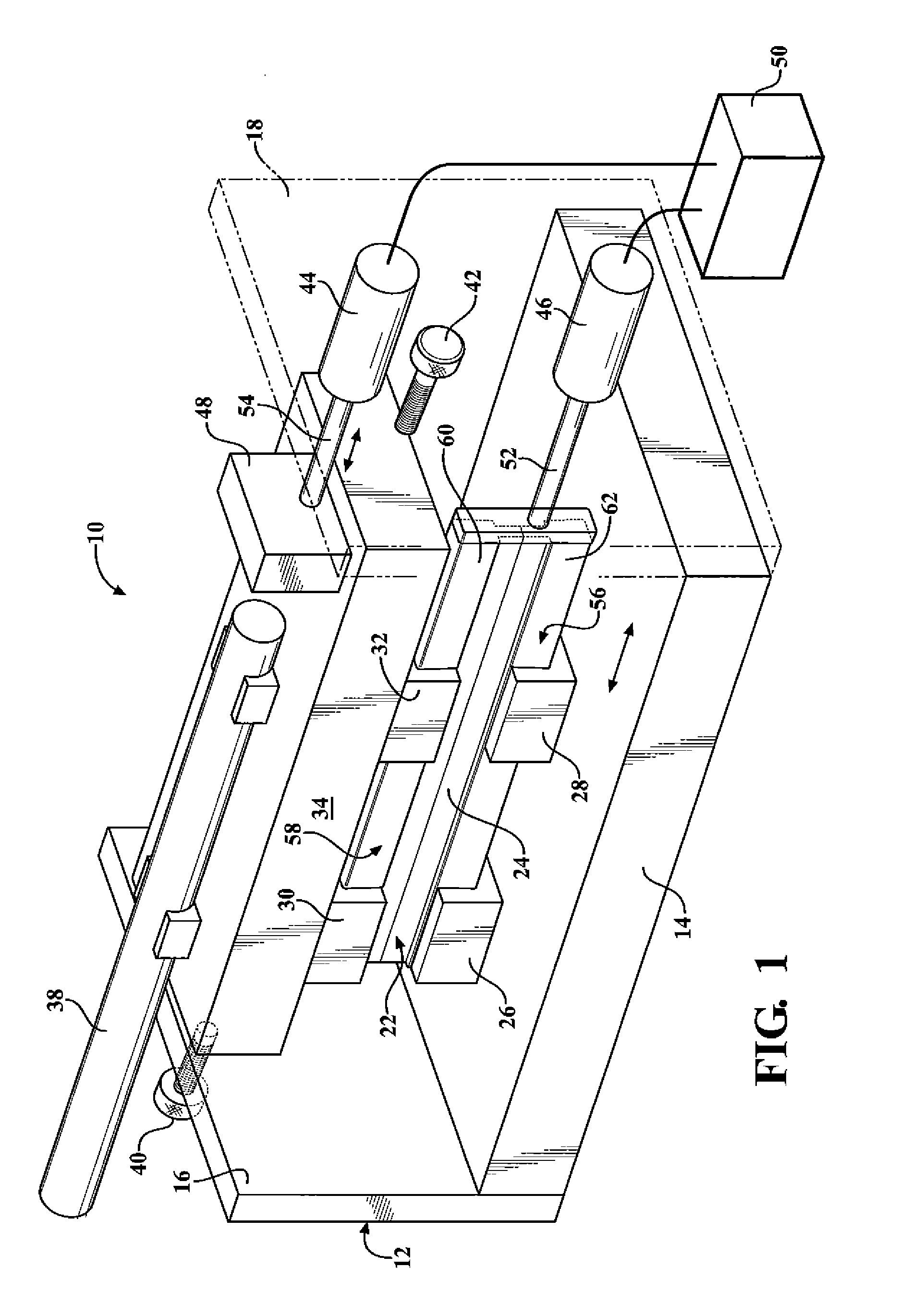
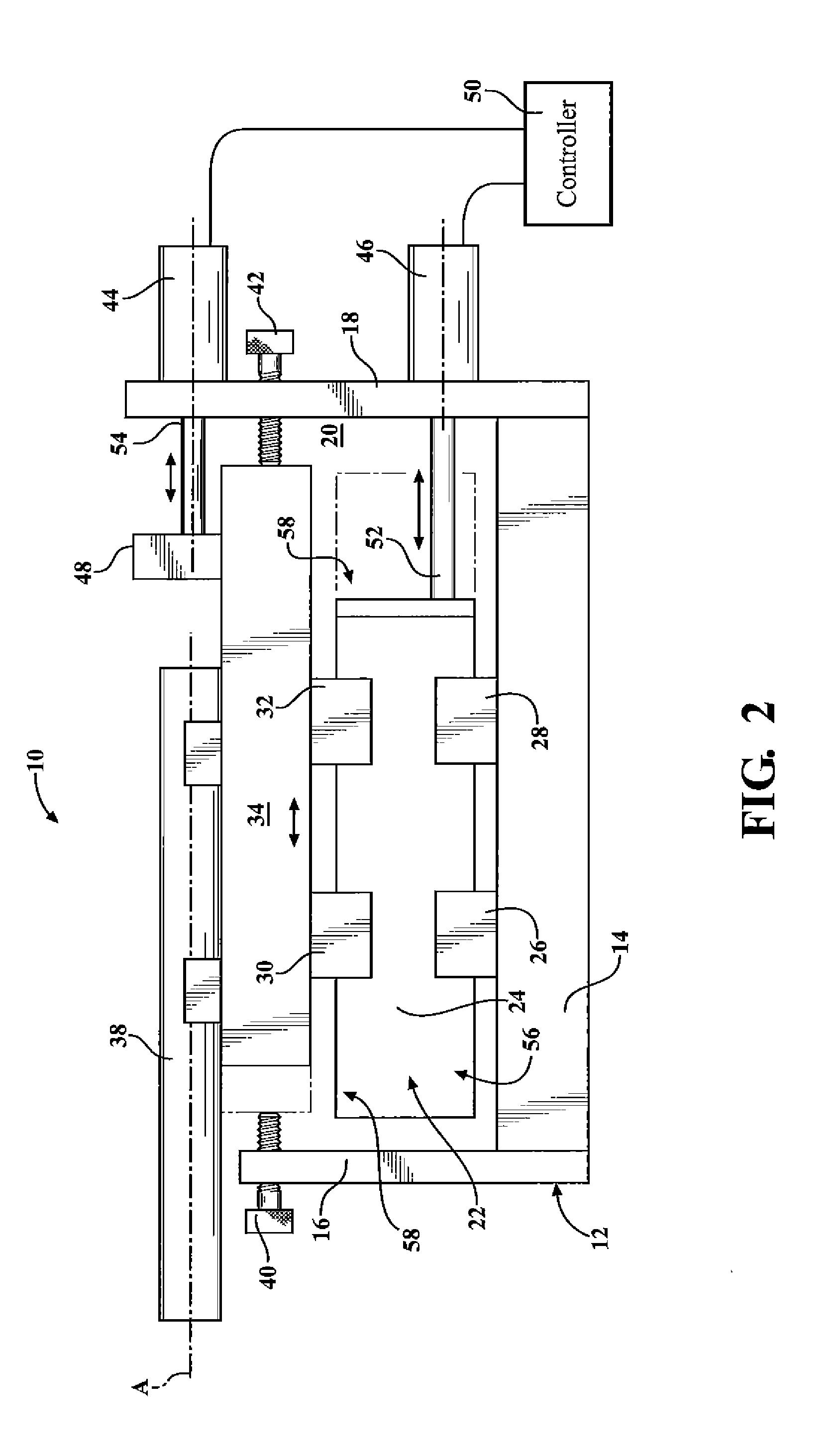
[0026]Referring to the Figures, wherein like numerals indicate like or corresponding parts throughout the several views, a linear bearing assembly (the assembly) of the present invention is generally shown at 10 in FIGS. 1-3. The assembly 10 has numerous applications including and not limited to applications that require excessive and repetitive linear motions, i.e. “pick and place” robotic, applications, various testing devices and the like. The assembly 10 illustrated and described herewith is not intended to limit the scope of the present invention and is depicted to disclose concept as applicable to all of the aforementioned applications.

[0027]The assembly 10 includes a housing, generally indicated at 12 presenting a support surface or base 14 having a pair of walls 16, 18 extending upwardly therefrom to form a chamber 20. A rail device, generally indicated at 22, is positioned within the chamber 20 and is supported by the base 14. The rail device 22 includes a rail 24, a pair o...


PUM

PropertyMeasurementUnit
Timeaaaaaaaaaa
Distanceaaaaaaaaaa
Deformation enthalpyaaaaaaaaaa

Abstract

A linear bearing assembly (the assembly) of the present invention is disposed in a housing of the assembly. A first rail and a second rail are movable relative to one another. A plurality of linear bearings are connected to the housing and disposed about the first and second rails. An actuator device is connected to at least one of the first rail and the second rail to selectively move the first rail and the second rail relative to one another and the housing in at least one of simultaneous and separate modes to redistribute lubricant in the linear bearings thereby preventing deformation of at least one of the first rail and the second rail.

Description

FIELD OF THE INVENTION[0001]The present invention relates generally to a linear bearing assembly and method of forming the same.BACKGROUND OF THE INVENTION[0002]Conventional linear bearing systems are widely used in various industrial applications that require motion between at least two parts. The linear bearing system typically includes an axially extending guide rail having rolling grooves in outer surfaces and a slider mounted over the guide rail. The slider includes a slider body and an end cap fitted at both ends of the slider body. The slider includes rolling elements disposed therein. The rolling elements, such as, for example, steel balls, are loaded in the circuits. Before an object connected to or supported by the slider can move, force has to be applied to the object until the resisting force due to static friction is overcome. This static friction is also called “stiction”.[0003]Once the object starts moving, the resisting force drops to a lower level dynamic friction f...

Claims


Application Information

Patent Timeline
IPC IPC(8): F16C29/06B23P17/00
CPCF16C29/008F16C29/04Y10T29/49641
Inventor EPSHETSKY, YEFIMROSAUER, MATHEW PETERHEINS, ANDREW WALTERSTILFIELD, RICHARD MCLEANSTILFIELD, LIEN PHAM
Owner AB SKF
Why Eureka
Try Eureka