Method for determining optimum vortex generator placement for maximum efficiency on a retrofitted wind turbine generator of unknown aerodynamic design

a technology of aerodynamic design and optimum placement, which is applied in the direction of machines/engines, mechanical equipment, instruments, etc., can solve the problems of complex control and equipment, consuming energy, and being subject to components failure, so as to improve the aerodynamic drag of the blade, improve the mixing effect, and improve the aerodynamic effect of the blad

Active Publication Date: 2012-06-21
INVENTUS HLDG
View PDF4 Cites 71 Cited by
  • Summary
  • Abstract
  • Description
  • Claims
  • Application Information

AI Technical Summary

Benefits of technology

[0017]The addition of VGs to a smooth blade induces instabilities to the airflow over the blade by creating counter-rotating vortices which enhance the mixing between the free air flow and the boundary layer (BL). The reenergized boundary layer is thus able to remain attached to the blade surface for a greater length along the chord. In this way the separation is delayed or even eliminated at the inner blade region with positive effects in blade performance. The implementation of VGs naturally

Problems solved by technology

These technologies require sophisticated controls and equipment, consume energy, are subject to failure of components, and are more costly than static methods.
As a result, typical parameters and “rules of thumb” that help to determine the placement and configuration of vortex generators on an airplane wing are not adequate or sufficiently reliable for determining the efficient placement and configuration of vortex generators on a turbine blade.
The result is that the blade may become an inefficient airfoil near the root, and incipient or actual stall conditions may significantly diminish the efficiency of the inner sections of the blade.
Such design details, however, are generally not disclosed by wind turbine blade manufacturers and may not be available upon request.
Where such simulations are not a practical solution, however, such as where a system is already in existence and is currently operating in the field, a different methodology may be employed.
Although Corten's method provides a visual represent

Method used


Image

  • Method for determining optimum vortex generator placement for maximum efficiency on a retrofitted wind turbine generator of unknown aerodynamic design
  • Method for determining optimum vortex generator placement for maximum efficiency on a retrofitted wind turbine generator of unknown aerodynamic design
  • Method for determining optimum vortex generator placement for maximum efficiency on a retrofitted wind turbine generator of unknown aerodynamic design

Examples


Embodiment Construction

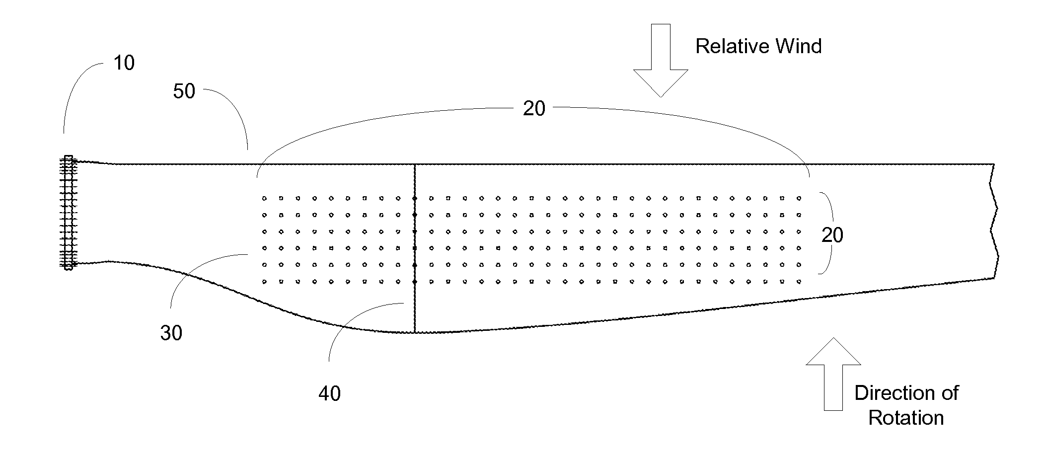
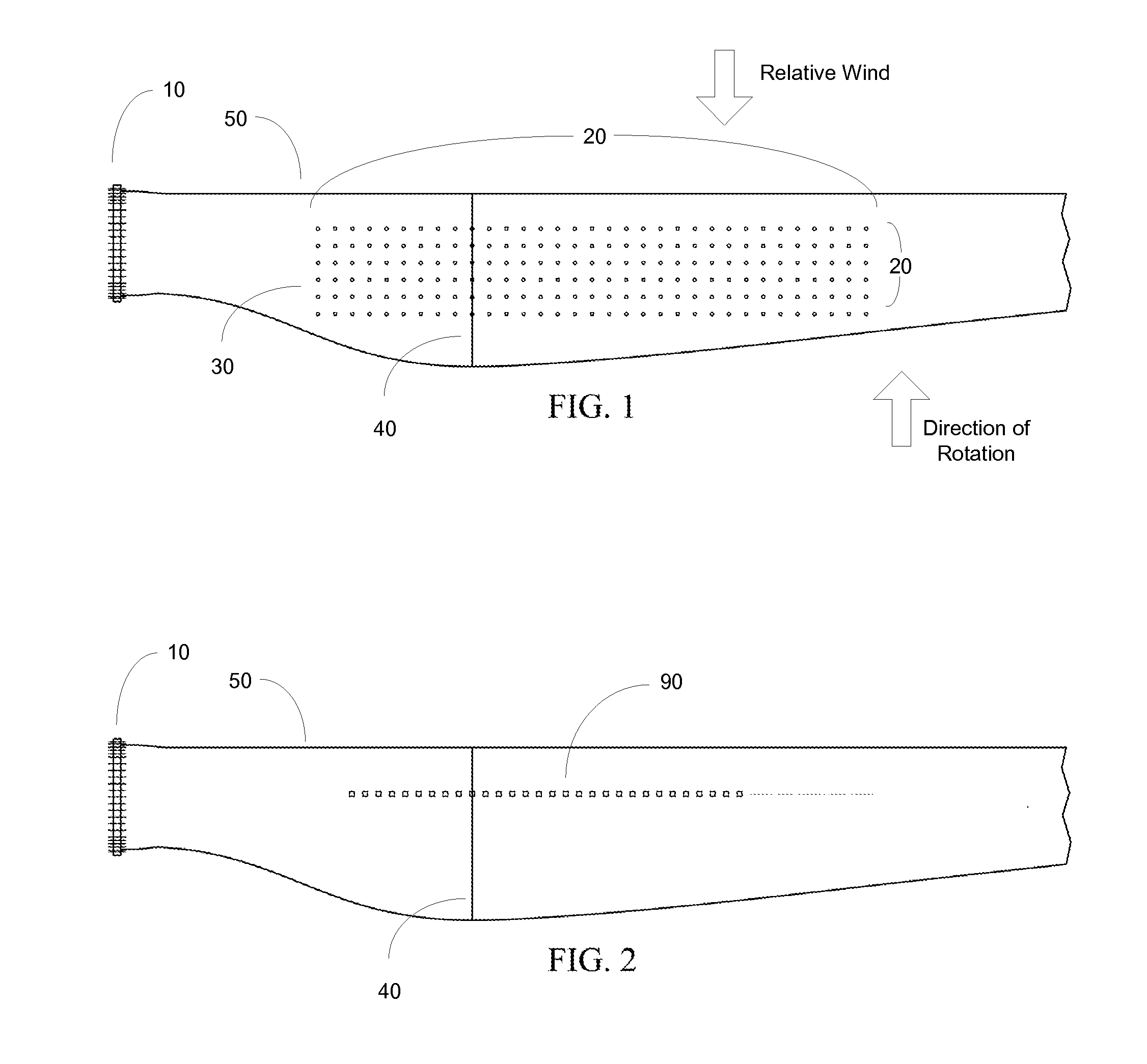
[0027]In FIG. 1, a portion of a blade having a representative length of approximately 37 m is viewed from a position directly perpendicular to the direction of blade rotation, which is upward in the diagram. As many of the aerodynamic concepts relating to wind turbine blades were developed through studies of airplane wings, the terms “wing” and “blade” may be used interchangeably herein except as otherwise noted. “Z” numbers indicate distances in mm from the blade root (Z=0) to various points along the span of the blade. The defined area for placement of VGs 20 is between 10% and 40% of the wing (blade) span, measured from the root 10, and from 20% to 70% of the maximum chord 40, measured from the leading edge 50. Stall flag (“telltale”) locations 30 are shown within the defined area 20 on the surface through a pattern of dots located between Z=3700 and Z=14,800 along the wingspan, and between 20% and 70% of the maximum chord distance 40 from the leading edge of the blade 50.

[0028]T...


PUM

PropertyMeasurementUnit
Fractionaaaaaaaaaa
Fractionaaaaaaaaaa
Fractionaaaaaaaaaa

Abstract

A method of optimizing performance of a wind turbine electric generator (WTG) comprises the steps of measuring the performance of a wind turbine electric generator, defining an area on a blade of the WTG, placing stall flags within said defined area, monitoring the behavior of the stall flags when the WTG is operating, determining a stall line based upon the stall flags during operation, installing vortex generators on the blade adjacent to and upwind of said stall line, monitoring the behavior of said stall flags during operation with vortex generators installed on all blades, and measuring the performance of the WTG to detect improved performance. If there is little or no improvement, repeating the steps on a second WTG using different placement within the defined area for the vortex generators.

Description

CROSS REFERENCE TO RELATED APPLICATIONS[0001]This application claims the benefit of U.S. Provisional Application No. 61 / 423,921 filed Dec. 16, 2010, the disclosure of which is hereby incorporated herein by reference in its entirety.BACKGROUND OF THE INVENTION[0002]As renewable energy has become an important economic and environmental imperative, the use of wind turbines to generate electricity on a commercial scale has assumed a role of increasing importance in the national and international arenas. While wind turbines, and the aggregation of wind turbines known as “wind farms,” have been in existence for years, current efforts to increase electrical generation capacity using existing equipment is a major focus for development in power systems. Although environmental conditions, such as lack of wind, gusting winds, sand storms, icing conditions, and extreme heat, are factors that cannot be controlled to any significant extent, there are modifications that can be made to existing sys...

Claims


Application Information

Patent Timeline
IPC IPC(8): B23P15/04G01L3/00
CPCY02E10/721Y10T29/49337F03D1/0608F05B2240/122F05B2240/3062Y02E10/72
Inventor BRAKE, DANIELHAMMITT, JEFFREYPECHLIVANOGLOU, GEORGIOS
Owner INVENTUS HLDG
Why Eureka
Try Eureka