
Gas storage apparatus

a technology of gas storage apparatus and gas storage container, which is applied in the direction of domestic cooling apparatus, lighting and heating apparatus, and container filling under pressure, etc. it can solve the problems of potentially hazardous cylinders, inability to meet the requirements of use, and risk of nitrous oxide actually freezing in the cylinder, etc., to facilitate the storage of substantial quantities of non-permanent gas

Inactive Publication Date: 2012-06-21
LINDE AG
View PDF8 Cites 3 Cited by
  • Summary
  • Abstract
  • Description
  • Claims
  • Application Information

AI Technical Summary

Benefits of technology

[0013]The plastic sachets preferably have a minimum of free space. Accordingly, at least 95% of the free space of the plastic sachets is occupied by the heat release substance in liquid state (at a temperature of 200 C). Any gas space acts as an insulator and is therefore to be avoided. A further precaution is to degas the heat release substance prior to introduction into the sachets or prior to sealing of the sachets. Such a measure avoids an ullage space being created or enlarged in the sachets as a result of natural degassing during use.
[0016]The heat release material is typically a substance which has a melting point in the range of 0-100 C and which is therefore in its liquid state at normal ambient temperatures. The function of the heat release substance is to prevent the liquid phase of the gas from sustaining a serious fall in temperature and pressure as it evaporates during delivery of gas. The heat release substance achieves this function by releasing heat to the liquefied gases as temperature attempts to fall.
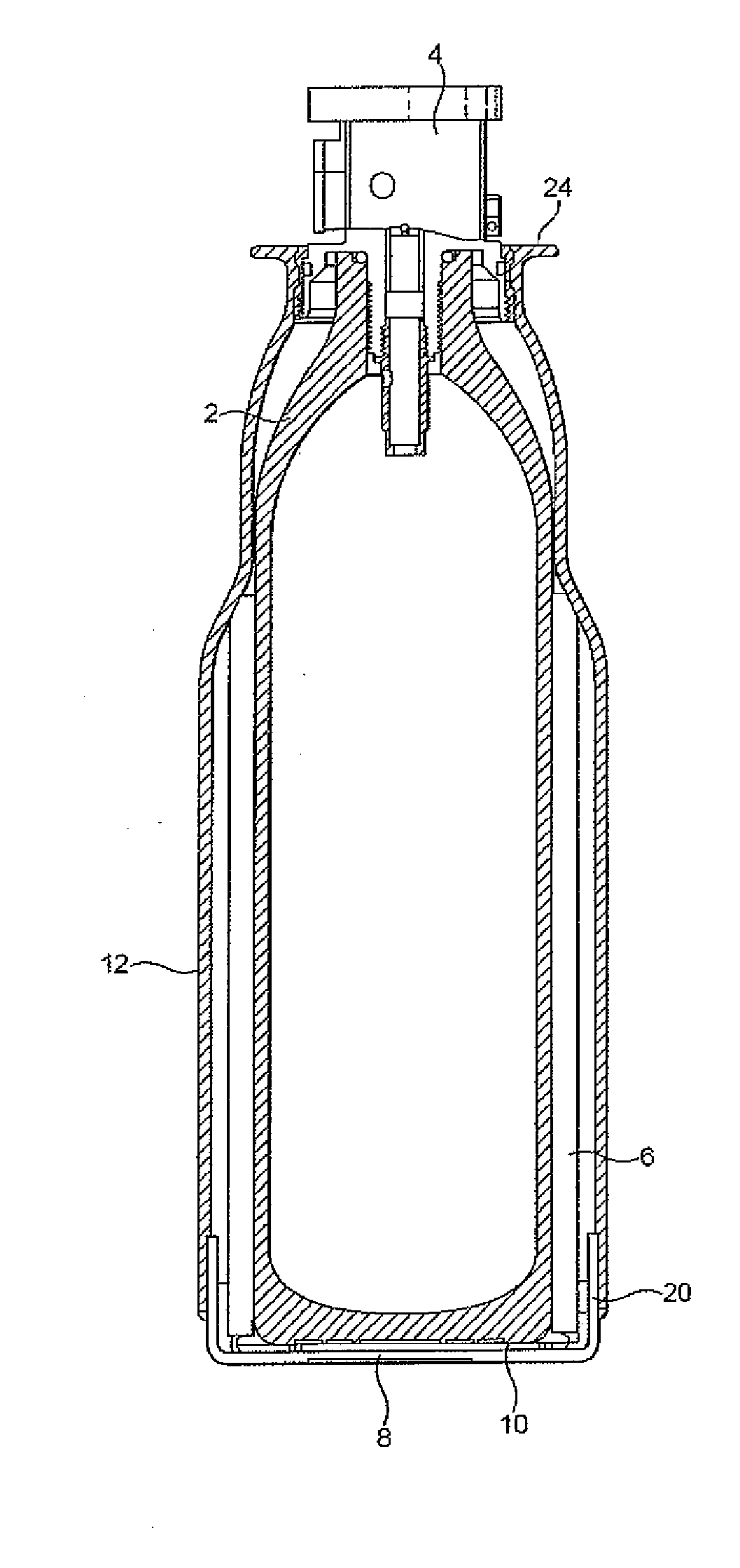
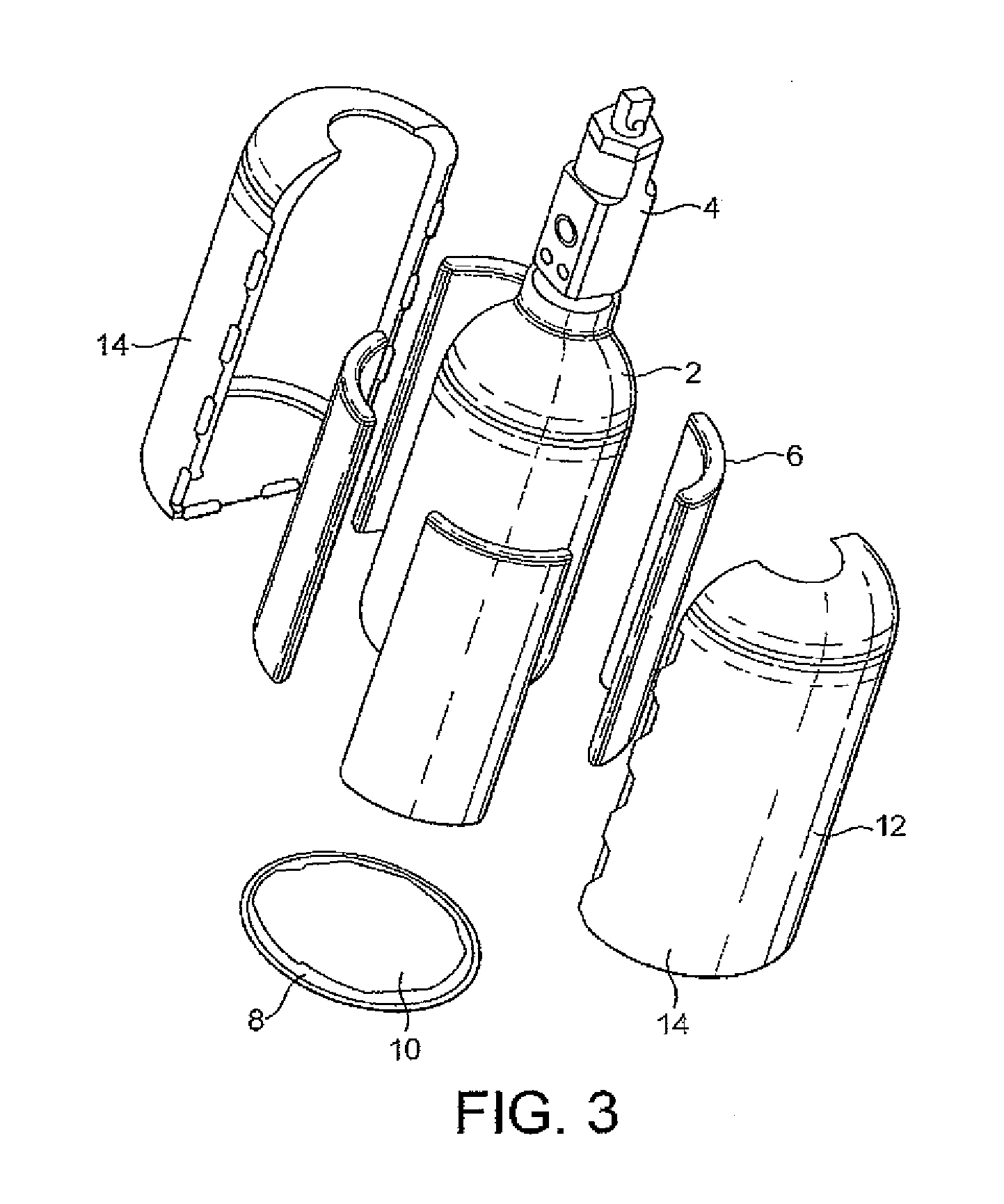
[0018]The gas storage apparatus typically additionally includes a cylindrical guard sleeve surrounding and spaced from the sachets. In this way the sachets are prevented from being punctured during normal handling of the vessel. The guard sleeve may be a one piece member or may comprise a plurality of members, for example, a pair of engaging semi-cylindrical members. The guard sleeve is typically formed of a transparent plastics material, particularly if it is desired to view writing or symbols on the exterior surface of the pressure vessel itself. The top of the guard sleeve typically engages a shoulder on the pressure vessel or the valve of the pressure vessel. It may also engage a base member in the form of a bowl in which the pressure vessel sits. Typically there is plastics sachet containing a heat release substance in thermal contact with the base of the pressure vessel. The plastics sachet at the base may be essentially the same as the other plastic sachets.
[0020]The gas supply apparatus according to the invention facilitates the storage of substantial quantities of non-permanent gas in lightweight vessels without giving rise to problems of restricted flow of the non-permanent gas when it is delivered from the pressure vessel and without creating unduly low temperatures at the surface of the pressure vessel.

Problems solved by technology

Particular problems, which will be outlined below, can arise when supplying a non-permanent gas from a pressurised gas storage vessel containing the non-permanent gas in liquid state under the pressure of a gaseous phase.
In practice, depending on the rate of gas removal, small cylinders can reach low temperatures such as −30 to −700 C. As a result, the cylinders become potentially hazardous as they would create a cold burn if they came into all but the most fleeting contact with human skin.
Further, low temperatures can cause problems downstream, through condensation on the equipment and the hardening and thus leakage of elastomeric seals.
However, a temperature drop of 80K is unacceptable because the external surface of the cylinder would be unsafe to touch owing to its low temperature and as the freezing point of nitrous oxide is approximately −80 C, there would be a risk of the nitrous oxide actually freezing within the cylinder.
Further, many elastomeric sealing materials harden and leak if subject to a temperature less than −300 C.
Simple solutions to the problem are not effective.
Thermally insulating the exterior of the cylinder would protect the user from cold burns, but exacerbate the temperature drop within the cylinder.
Increasing the weight of the cylinder would reduce the temperature drop, but this may add unacceptably to the overall weight of the equipment.
Prolonged contact of the buffer substance with the gas vessel may cause corrosion or erosion of the surface of the latter.
Further, over a period of time the buffer substance becomes depleted by evaporation.

Method used


Image

  • Gas storage apparatus
  • Gas storage apparatus
  • Gas storage apparatus

Examples


Embodiment Construction

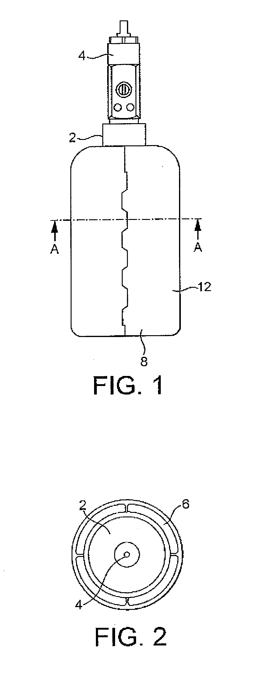
[0029]Referring to FIGS. 1 to 3, the illustrated gas release apparatus comprises a pressure vessel in the form of lightweight gas cylinder 2, typically formed of aluminium. The cylinder typically has a water capacity of 1 l or less, typically 0.5 l. The cylinder contains a non-permanent gas, for example, nitrous oxide or carbon dioxide. The non-permanent gas is stored under pressure and is present both in the gaseous phase and the liquid phase, most of the molecules of the non-permanent gas being present in the liquid phase. The total weight of a full cylinder 2 is such that it can be readily lifted and held by hand. The cylinder 2 may therefore be made of, for example, aluminium.

[0030]The cylinder is closed by a valve 4, which may be manually or automatically operable to deliver gas, when desired. The valve 4 may be of the tamper-proof kind described in WO-A-2009 / 125180, the disclosure of which is incorporated herein by reference. The gas cylinder 2 is not provided with a dip tube....


PUM


Abstract

A gas storage apparatus comprises a pressure vessel in the form of a cylinder, closed by a valve, containing a non-permanent gas having under its storage conditions a gas phase and a liquid phase. A jacket formed of plastics sachets surrounds and is in heat transfer relationship with the outer surface of the cylinder. The sachets define closed compartments containing a heat release substance which is liquid at 20° C. On opening the valve, the non-permanent gas is delivered from the cylinder. The liquid phase of the non-permanent gas absorbs heat from the heat release substance which undergoes fusion. The heat release substance may be water.

Description

FIELD OF THE INVENTION[0001]This invention relates to a gas storage apparatus for storing under pressure a non-permanent gas with some of the gas being present in a liquid phase and the rest in a gas phase.BACKGROUND OF THE INVENTION[0002]Pressurised gas storage vessels are very well known and are often called “gas cylinders” even if not of cylindrical shape. The pressurised gas storage vessel can be used to store a permanent gas, that is a gas which cannot be liquefied by the application of pressure alone, or a non-permanent gas, that is a gas which can be liquefied by the application of pressure alone. Examples of non-permanent gases are carbon dioxide and nitrous oxide.[0003]Particular problems, which will be outlined below, can arise when supplying a non-permanent gas from a pressurised gas storage vessel containing the non-permanent gas in liquid state under the pressure of a gaseous phase. Because the molecules of the non-permanent gas will be contained in the liquid phase, it...

Claims


Application Information

Patent Timeline
IPC IPC(8): F17C1/00
CPCF17C1/14F17C2270/02F17C2201/0119F17C2201/032F17C2201/058F17C2203/0362F17C2203/037F17C2203/0617F17C2203/0646F17C2205/0115F17C2205/0126F17C2205/0165F17C2221/01F17C2221/013F17C2223/0153F17C2223/035F17C2223/043F17C2225/0123F17C2225/035F17C2227/0316F17C2227/0386F17C2260/032F17C2201/0109
Inventor TATAREK, ANDREW RICHARD THOMAS
Owner LINDE AG
Learn More