Vaporizer heating assembly

a heating assembly and vaporizer technology, applied in the field of vaporizers, can solve the problems of unoptimized adverse effects on user experience, and inability to optimize airflow and/or heat exchange, so as to achieve the effect of maximizing heat transfer efficiency

Inactive Publication Date: 2012-06-21
VAPORFECTION INT
View PDF14 Cites 19 Cited by
  • Summary
  • Abstract
  • Description
  • Claims
  • Application Information

AI Technical Summary

Benefits of technology

[0005]The invention provides a vaporizer heating assembly that overcomes the hereinafore-mentioned disadvantages of the heretofore-known devices and methods of this general type and that maximizes efficiency of heat transfer between a heating element and a passing stream of air. The invention also provides proved consistency of heating-element temperature monitoring and control.

Problems solved by technology

Prior-art vaporizers use a heating element that adds an unpleasant taste to the air stream flowing through it.
In addition, all known vaporizers are made with a heating element inside an air-flow conduit where the heating element rests against a portion of the interior of the conduit, thereby preventing air from flowing around certain portions of the heating element, resulting in non-optimized airflow and / or heat exchange.
The temperature controllers attached to the probes respond to this temperature change, often unnecessarily and too severely, thereby resulting in a sinusoidal pattern in the heating taking place within the heating element, resulting in too high or too low of temperatures and adverse effects to the user's experience.

Method used


Image

  • Vaporizer heating assembly
  • Vaporizer heating assembly
  • Vaporizer heating assembly

Examples


Embodiment Construction

[0033]While the specification concludes with claims defining the features of the invention that are regarded as novel, it is believed that the invention will be better understood from a consideration of the following description in conjunction with the drawing figures, in which like reference numerals are carried forward. It is to be understood that the disclosed embodiments are merely exemplary of the invention, which can be embodied in various forms.

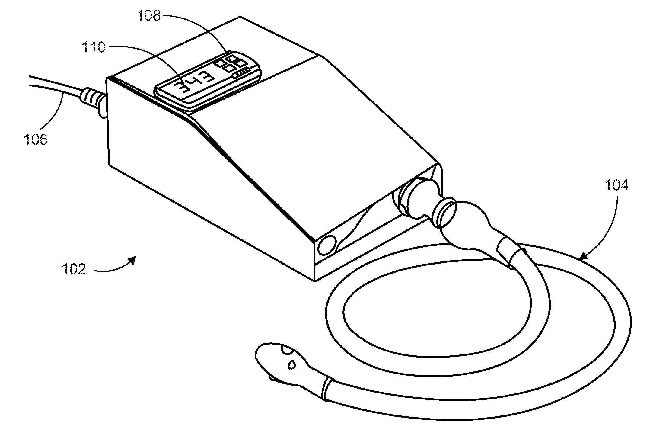
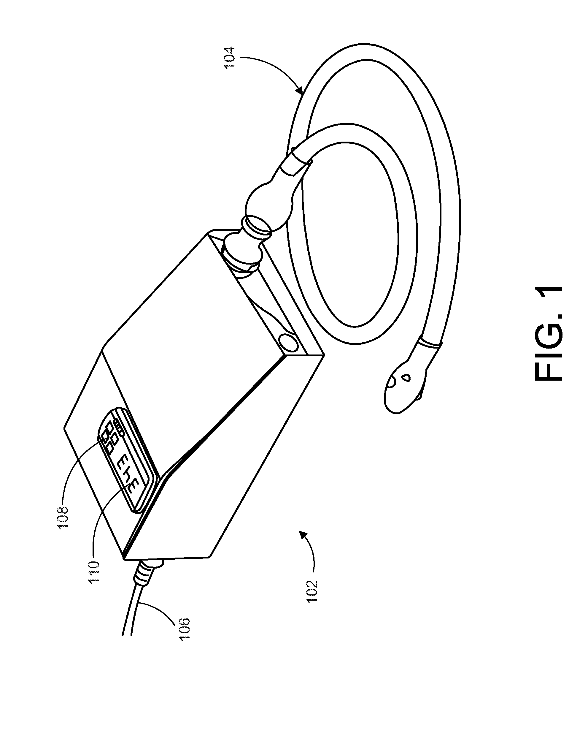
[0034]The present invention provides a novel and efficient heating element assembly and accurate and stable temperature control of said element. Embodiments of the invention provide a glass-on-glass heating element configuration that optimizes heat transfer to a passing flow of air. In addition, embodiments of the invention provide a temperature sensor and control circuit for monitoring the inventive heating element and providing optimized temperature stability and control.

[0035]Referring now to FIG. 1, one embodiment of the present in...


PUM


Abstract

A vaporizer heating assembly includes an airflow chamber having a proximal end, a distal end opposite the proximal end, and a glass body connecting the proximal end to the distal end. A heating chamber is located within the airflow chamber and includes an elongated glass body and a heating element located within the elongated glass body of the heating chamber. A fan is in fluid communication with the proximal end of the airflow chamber and an attachment adapter is mechanically coupled to the distal end of the airflow chamber in a sealing arrangement, where the attachment adapter forms an attachment port for a vapor receiving element.

Description

FIELD OF THE INVENTION[0001]The present invention relates generally to a vaporizer for inhalation of active ingredients within a plant material, and more particularly relates to a heating assembly within a vaporizer that provides improved airflow, longer life, reduced taste emissions, and superior temperature control.BACKGROUND OF THE INVENTION[0002]A vaporizer is a device used to extract the active ingredients of plant material, e.g., cannabis, tobacco, or other herbs or blends, for inhalation by a human. Vaporization involves heating a material so that its active compounds boil off into a vapor. As opposed to smoking, i.e., burning, vaporization avoids the production of irritating, toxic, and carcinogenic by-products. In fact, no combustion occurs, so no smoke or taste of smoke is present. Studies show that vapor contains substantially zero particulate matter or tar, and, in comparison to smoking, significantly lower concentrations of noxious gases such as carbon monoxide. It has ...

Claims


Application Information

Patent Timeline
Patent Type & Authority Applications(United States)
IPC IPC(8): A61M16/00
CPCA61M11/041A61M15/06A61M16/0066A61M2205/3368A61M16/1095A61M11/04F28D7/10A61M11/042F28D7/106
Inventor YOMTOV, AMIR
Owner VAPORFECTION INT
Why Eureka
Try Eureka