
Bumper for air spring

a technology of air springs and bumpers, which is applied in the direction of resilient suspensions, suspension arms with pivoted, vehicle springs, etc., can solve the problems of increasing production costs with a considerable amount, increasing the risk of breaking these parts, and increasing the production cost. , to achieve the effect of reducing production costs, reducing cost and labor, and reducing production costs

Inactive Publication Date: 2012-06-21
AKTAS HAVA SUSPANSIYON SISTEMLERI SANAYI & TICARET ANONIM SIRKETI
View PDF13 Cites 15 Cited by
  • Summary
  • Abstract
  • Description
  • Claims
  • Application Information

AI Technical Summary

Benefits of technology

The present invention provides a method for producing a bottom plate and bumper for air suspension systems using reinforced plastic material in a single body. This decreases production costs and minimizes loss of cost and labor due to additional connection apparatus and methods. The invention also eliminates the need for welding, which is commonly used to fix bumpers and bottom plates in present techniques. The bottom plate with bumper is made of reinforced plastic material and is mounted to the piston after being vulcanized to the elastomeric bellows. The production method involves placing a metal connection apparatus into a mold of a plastic injection machine and covering the connection part with reinforced plastic material during the plastic injection process.

Problems solved by technology

If the bumper is not used, the whole weight of the vehicle chassis will be loaded onto the piston or bottom plate without absorbing, and in this case the breaking risk of these parts will be increased.
So that the security problems will be occurred.
Also it increases the production cost with a considerable amount.
Thus the labor costs and production costs increase and production speed decreases.

Method used


Image

  • Bumper for air spring
  • Bumper for air spring
  • Bumper for air spring

Examples


Embodiment Construction

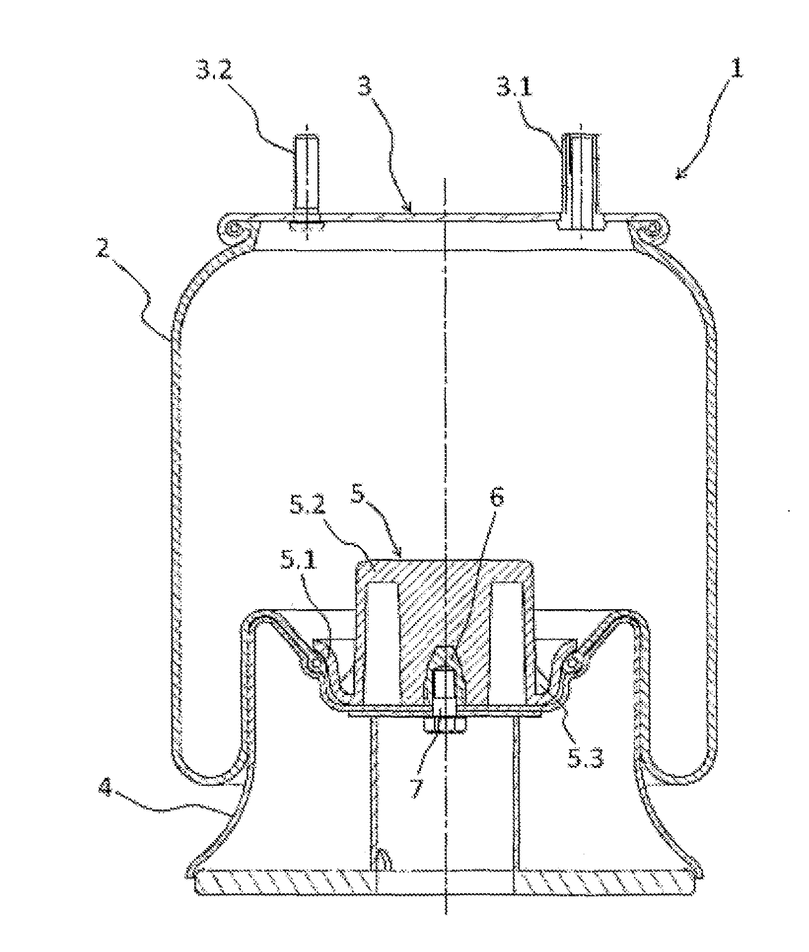
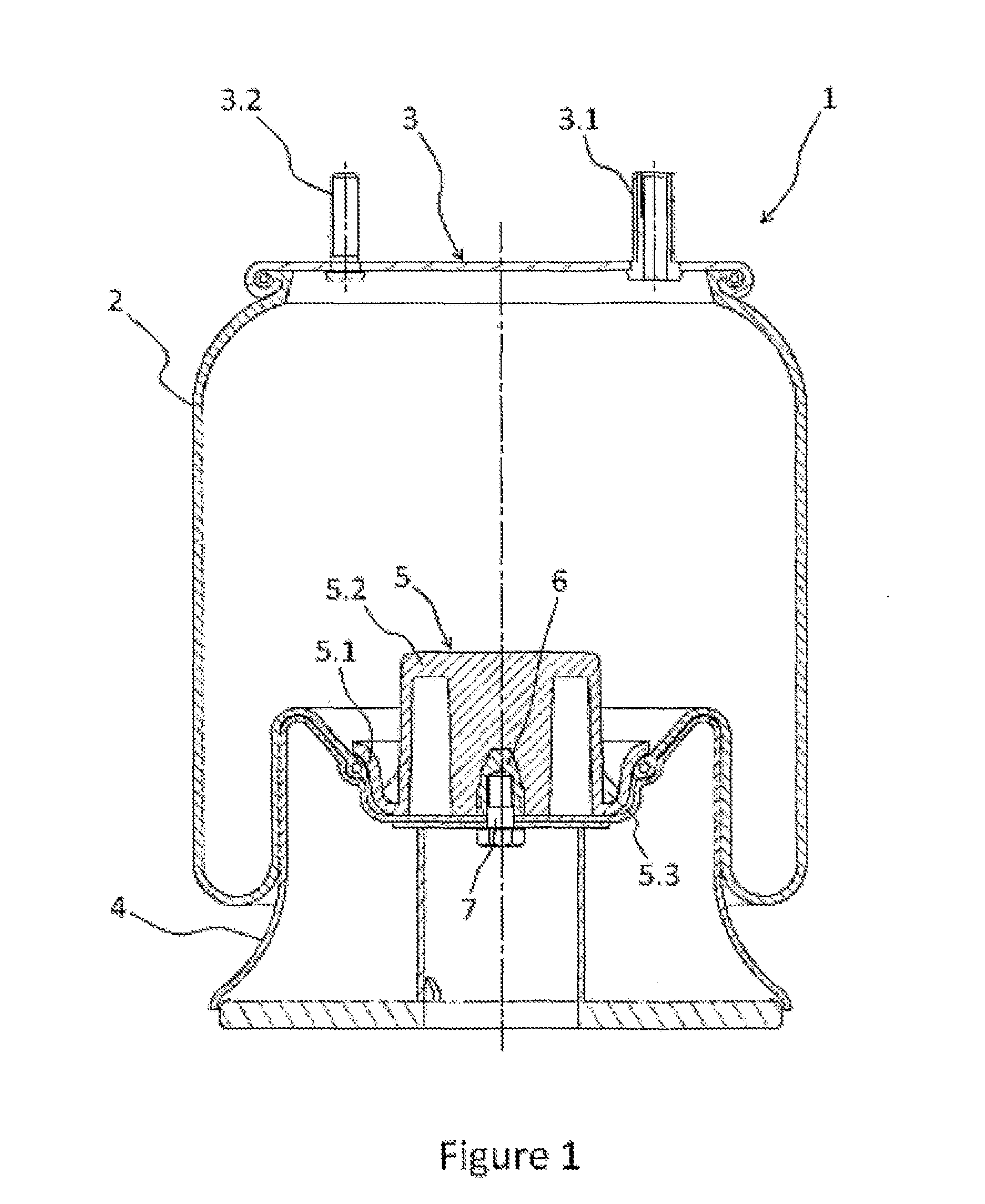
[0046]In FIG. 1, the perspective view of the air suspension system (1) is given. Air suspension systems (1) generally comprise a plastic or metal piston (4) fixed to the vehicle axle and an elastomeric bellows (2) which is air tightly vulcanized from its lower open end to the upper part of the piston (4) and from its upper open end to the metal plate (3) fixed to the vehicle chassis. The lower and upper open ends of the elastomeric bellows (2) are fixed onto the piston (4) and plate (3) in air-tightly manner. Thanks to this, a pressured air chamber is formed inside the elastomeric bellows (2), which absorbs the loads and the vibrations occurred during the vehicle motion.

[0047]There is an air inlet hole (3.1) on the plate (3) to fill the pressured air into the elastomeric bellows (2) or to discharge the pressured air inside the bellows (2) to the outside. Further, there are connection bolts (3.2) on the plate (3) to provide the connection between the plate (3) and the vehicle chassis...


PUM

PropertyMeasurementUnit
resistanceaaaaaaaaaa
heightaaaaaaaaaa
volumeaaaaaaaaaa

Abstract

An air suspension system includes a plastic or metal piston fixed to the vehicle axle and an elastomeric bellows which is air tightly vulcanized from its lower open end to the upper part of the piston and from its upper open end to the metal plate fixed to the vehicle chassis to form a pressured air chamber and a single-piece bottom plate with bumper, which is completely made of reinforced plastic material. The air suspension system includes a compression part vulcanized to the elastomeric bellows and a bumper part absorbing the loads and which is mounted to the upper side of the piston after that it is vulcanized to the lower open end of the elastomeric bellows.

Description

CROSS-REFERENCE TO RELATED U.S. APPLICATIONS[0001]Not applicable.STATEMENT REGARDING FEDERALLY SPONSORED RESEARCH OR DEVELOPMENT[0002]Not applicable.NAMES OF PARTIES TO A JOINT RESEARCH AGREEMENT[0003]Not applicable.REFERENCE TO AN APPENDIX SUBMITTED ON COMPACT DISC[0004]Not applicable.BACKGROUND OF THE INVENTION[0005]1. Field of the Invention[0006]The present invention relates to air suspension systems which are used in transport vehicles such as articulated lorry, autobus, tractor, semi-trailer to provide constant vehicle height under all loading conditions, higher spring capability, ride comfort and vehicle level parallel to the road even with unbalanced loadings.[0007]The present invention especially relates to the production of the bottom plate and bumper used in air suspension systems as a single-piece.[0008]2. Description of Related Art[0009]Including Information Disclosed Under 37 CFR 1.97 and 37 CFR 1.98.[0010]Air suspension systems which are mounted between the chassis and...

Claims


Application Information

Patent Timeline
Patent Type & Authority Applications(United States)
IPC IPC(8): B60G11/27B29C45/14F16F9/05
CPCB60G7/04B60G11/27B60G11/28B60G2202/143F16F9/052B60G2204/126B60G2204/4502B60G2206/424F16F9/0454B60G2202/152
Inventor SIGIRTMAC, TAYFUNSERT, MESUT
Owner AKTAS HAVA SUSPANSIYON SISTEMLERI SANAYI & TICARET ANONIM SIRKETI
Learn More