Spark plug and method for producing spark plug

a technology of spark plugs and spark plugs, which is applied in the field of spark plugs, can solve the problems of dielectric strength and mechanical strength deterioration of insulations, and achieve the effects of reducing the length of the groove portion, and reducing the amount of radial deformation of the groove portion

Active Publication Date: 2012-06-21
NGK SPARK PLUG CO LTD
View PDF2 Cites 9 Cited by
  • Summary
  • Abstract
  • Description
  • Claims
  • Application Information

AI Technical Summary

Benefits of technology

[0028]In the course of crimping, the groove portion located between the tool engagement portion and the large-diameter portion contracts along the axial direction and is radially deformed in a curving manner. When the amount of radial deformation of the groove portion is excessively large, the outside diameter of the groove portion may become larger than the diameter of the inscribed circle of the recesses of the tool engagement portion, potentially resulting in a failure to properly engage a tool with the tool engagement portion. Thus, in order to reduce the amount of radial deformation of the groove portion, reducing the length of the groove portion is conceived. However, when the length of the groove portion is reduced excessively relative to the thickness of the groove portion, in the course of crimping, the groove portion is hardly deformed radially. As a result, stress which is axially applied to the tool engagement portion from the groove portion increases, potentially resulting in a deformation of the tool engagement portion.
[0029]In this connection, according to the above configuration 6, the groove portion has a sufficient thickness T of 0.7 mm or greater; thus, in the course of crimping, the amount of radial deformation of the groove portion can be relatively small. Furthermore, since the relational expression 3.0≦H / T is satisfied; i.e., the length of the groove portion is large to some extent relative to the thickness of the groove portion, in the course of crimping, there can be effectively restrained axial application of an excessively large stress to the tool engagement portion from the groove portion. As a result, an excessive increase in the outside diameter of the groove portion and a deformation of the tool engagement portion can be more reliably prevented, so that a tool can be engaged properly with the tool engagement portion in a more reliable manner.
[0030]In view of prevention of a deformation of the tool engagement portion, it is effective that the length of the groove portion is large to some extent relative to the thickness of the groove portion. However, when the length of the groove portion is excessively large relative to the thickness of the groove portion, an axial force which the metallic shell applies to the insulator drops, potentially resulting in breakage of gastightness between the metallic shell and the insulator.
[0031]In view of the above point, according to the above configuration 6, the length H of the groove portion is determined so as to satisfy the relational expression H / T≦5.5. Thus, coupled with the thickness T being 0.7 mm or greater, an axial force which the metallic shell applies to the insulator can be sufficiently large. As a result, deterioration in gastightness can be more reliably prevented.

Problems solved by technology

As a result, the insulator may deteriorate in dielectric strength and mechanical strength.

Method used


Image

  • Spark plug and method for producing spark plug
  • Spark plug and method for producing spark plug
  • Spark plug and method for producing spark plug

Examples


Embodiment Construction

Modes for Carrying Out the Invention

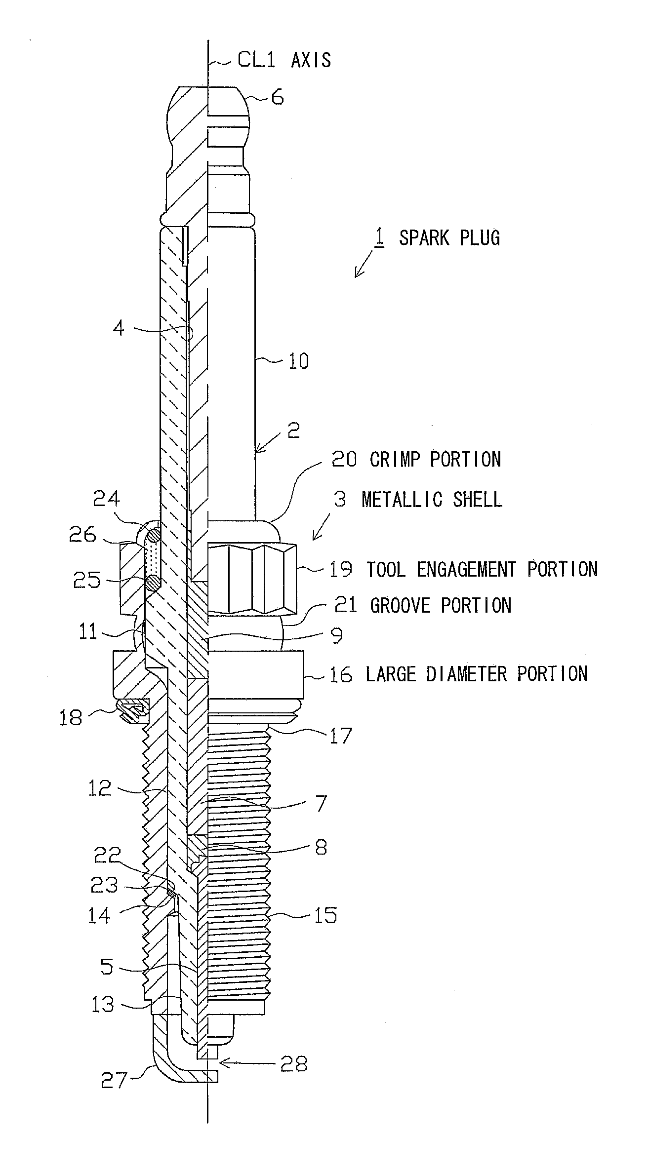
[0046]An embodiment of the present invention will next be described with reference to the drawings. FIG. 1 is a partially cutaway front view showing a spark plug 1. In FIG. 1, the direction of an axis CL1 of the spark plug 1 is referred to as the vertical direction. In the following description, the lower side of the spark plug 1 in FIG. 1 is referred to as the front side of the spark plug 1, and the upper side as the rear side.

[0047]The spark plug 1 includes a tubular ceramic insulator (insulator) 2 and a tubular metallic shell 3, which holds the ceramic insulator 2 therein.

[0048]The ceramic insulator 2 is formed from alumina or the like by firing, as well known in the art. The ceramic insulator 2, as viewed externally, includes a rear trunk portion 10 formed on the rear side; a flange portion 11, which is located frontward of the rear trunk portion 10 and projects radially outward; an intermediate trunk portion 12, which is located frontward of ...


PUM


Abstract

A spark plug includes a tubular metallic shell extending in the direction of an axis and having a tool engagement portion formed through extrusion. The tool engagement portion has a 12-point shape which is a sectional shape taken orthogonally to the axis and has a plurality of protrusions and recesses provided alternately. As viewed in a section taken orthogonally to the axis, when D (mm) represents the diameter of a circle which passes radially through the outermost positions on the protrusions, and d (mm) represents the diameter of a circle which passes radially through the innermost positions on the recesses, the relational expression 0.45≦(D−d)/2≦0.75 is satisfied. The spark plug can provide a more reliable restraint on the slippage of a tool at the time of mounting and enables the tool engagement portion to be reliably formed so as to form a desired shape.

Description

CROSS-REFERENCE TO RELATED PATENT APPLICATIONS[0001]This application is a U.S. National Phase Application under 35 U.S.C. §371 of International Patent Application No. PCT / JP2010 / 065542, filed Sep. 9, 2010, and claims the benefit of Japanese Patent Application No. 2009-244216, filed Oct. 23, 2009, all of which are incorporated by reference herein. The International Application was published in Japanese on Apr. 28, 2011 as International Publication No. WO / 2011 / 048882 under PCT Article 21(2).FIELD OF THE INVENTION[0002]The present invention relates to a spark plug for use in an internal combustion engine, etc., and to a method for producing the spark plug.BACKGROUND OF THE INVENTION[0003]A spark plug is mounted to, for example, a combustion apparatus, such as an internal combustion engine, for igniting an air-fuel mixture contained in a combustion chamber. Generally, a spark plug includes an insulator having an axial bore; a center electrode inserted into a front end portion of the axi...

Claims


Application Information

Patent Timeline
Patent Type & Authority Applications(United States)
IPC IPC(8): H01T13/12H01T21/02
CPCH01T13/12F02P13/00H01T13/02H01T13/36H01T21/02
Inventor KATO, TOMOAKI
Owner NGK SPARK PLUG CO LTD
Why Eureka
Try Eureka