Apparatus for monitoring operation state of battery pack composed of plurality of cells mutually connected in series

a technology of battery pack and operation state, which is applied in the direction of electrochemical generators, instruments, transportation and packaging, etc., can solve the problems of affecting the life of the cells, a long time before all the cell voltages are detected, and the failure of the cell to be located, so as to achieve the effect of high internal resistance, fast monitoring and good accuracy

Active Publication Date: 2012-06-21
DENSO CORP
View PDF5 Cites 12 Cited by
  • Summary
  • Abstract
  • Description
  • Claims
  • Application Information

AI Technical Summary

Benefits of technology

[0021]According to another typical embodiment, a battery-state monitoring apparatus is provided, which apparatus detects cell voltages of a plurality of cells connected in series and monitors a state of each of the plurality of cells based on the detected corresponding cell voltage. The apparatus includ...

Problems solved by technology

However, since the outputs of the comparators are ORed, there is a problem that the cell having a failure cannot be located.
Thus, it takes a long time before all of the cell voltages are detected.
Therefore, th...

Method used


Image

  • Apparatus for monitoring operation state of battery pack composed of plurality of cells mutually connected in series
  • Apparatus for monitoring operation state of battery pack composed of plurality of cells mutually connected in series
  • Apparatus for monitoring operation state of battery pack composed of plurality of cells mutually connected in series

Examples


first embodiment

[0033]Referring to some drawings, hereinafter, a first embodiment of the present invention is described.

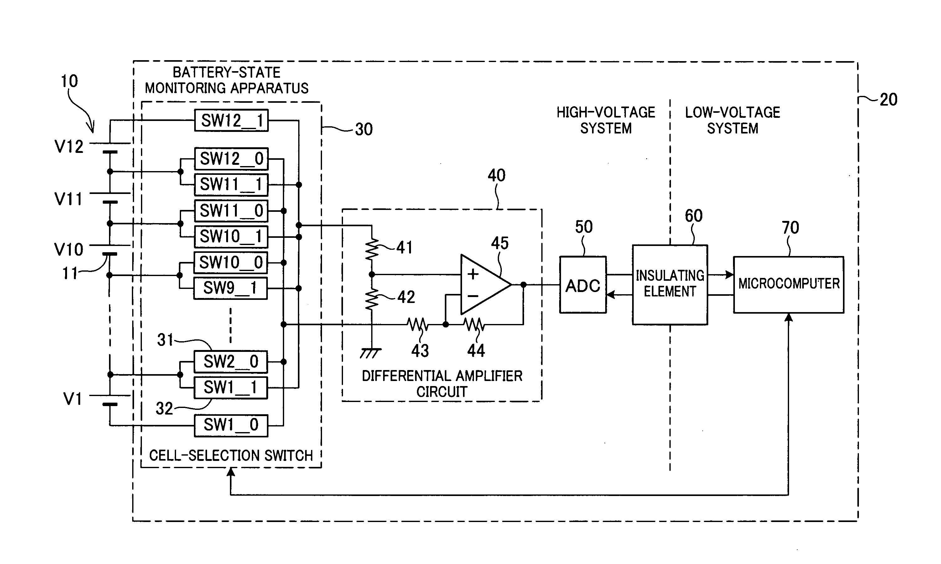
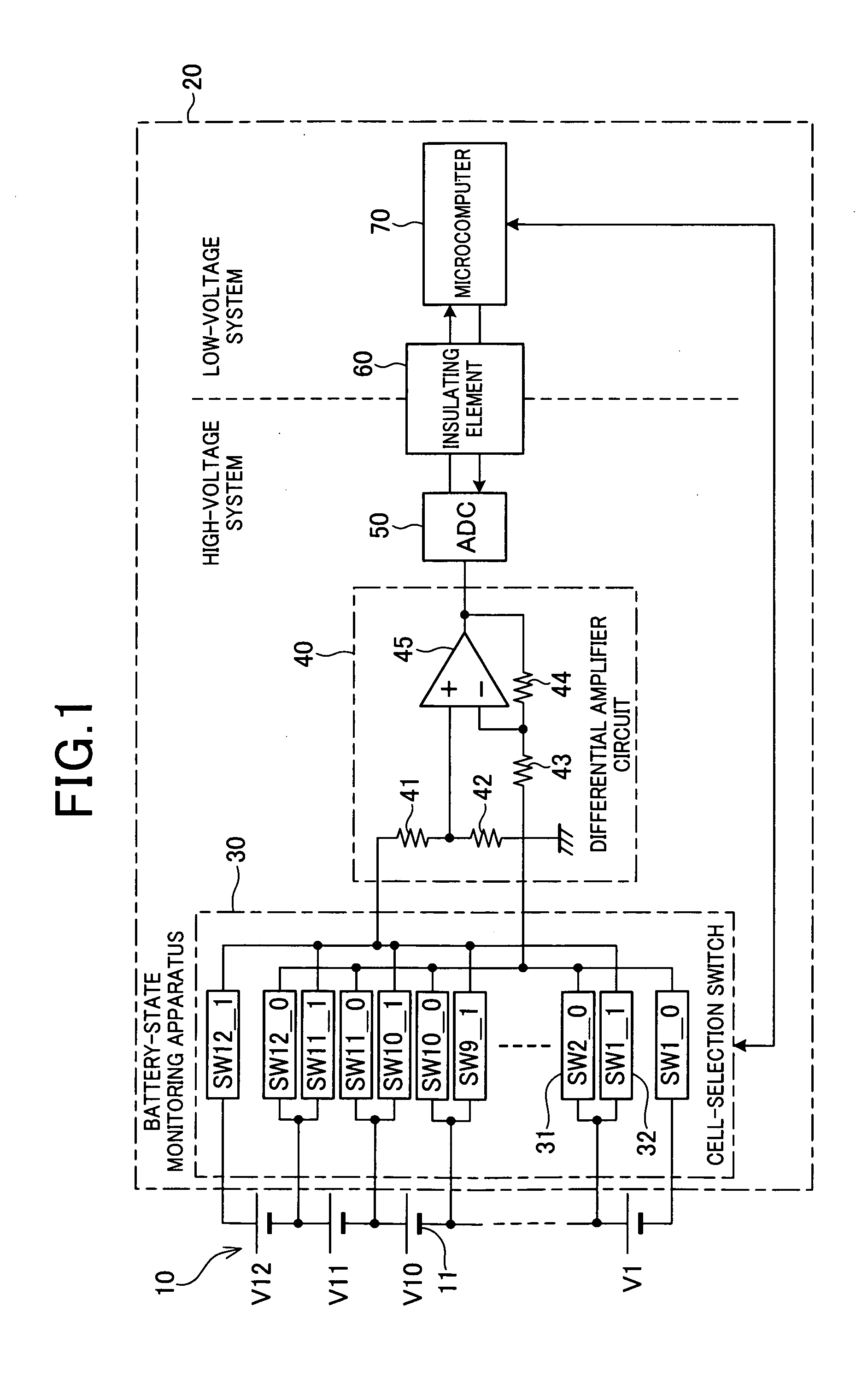
[0034]FIG. 1 is a schematic diagram illustrating a general configuration of a battery-state monitoring system that includes a battery-state monitoring apparatus according to the present invention. As shown in the figure, the battery-state monitoring system includes a battery pack 10 and a battery-state monitoring apparatus 20.

[0035]The term “battery state” used here, the term is defined as “an operation state inside the battery pack 10” as to whether the battery is in a state of normally supplying predetermined electric power. The voltage (cell voltage) of each of the cells is checked to obtain a piece of information regarding the operation state.

[0036]The battery pack 10 is a group of cells composed of a plurality of minimum-unit cells 11 connected in series. For example, twelve cells 11 (V1 to V12) are connected in series. Rechargeable lithium ion secondary cells are used as the...

second embodiment

[0065]Referring to FIGS. 3 to 6, hereinafter is described a battery-state monitoring apparatus according to a second embodiment.

[0066]In the present embodiment, differences from the first embodiment are described. In the second and the subsequent embodiments, components identical with or similar to the components described in the previous embodiment are given the same references to omit or simplify the description.

[0067]In the first embodiment described above, cell voltages have been detected using the method based on total-cell-voltage detection. In the present embodiment, however, the method based on total-cell-voltage detection is combined with the method based on comparators to ensure monitoring of the operation states of the cells 11.

[0068]FIG. 3 is a schematic diagram illustrating a battery-state monitoring system including a battery-cell monitoring apparatus 20 according to the present embodiment. As shown in FIG. 3, the battery-state monitoring apparatus 20 includes a compar...

third embodiment

[0099]Referring to FIGS. 7A and 7B as well as FIG. 8, hereinafter is described a battery-state monitoring apparatus according to a second embodiment. In the present embodiment, description will be given focusing on the differences from the second embodiment.

[0100]FIG. 7A is a schematic diagram illustrating a cell-number generation circuit 94 according to the present embodiment. FIG. 7B is a diagram illustrating an example of a SIN signal outputted from the cell-number generation circuit 94.

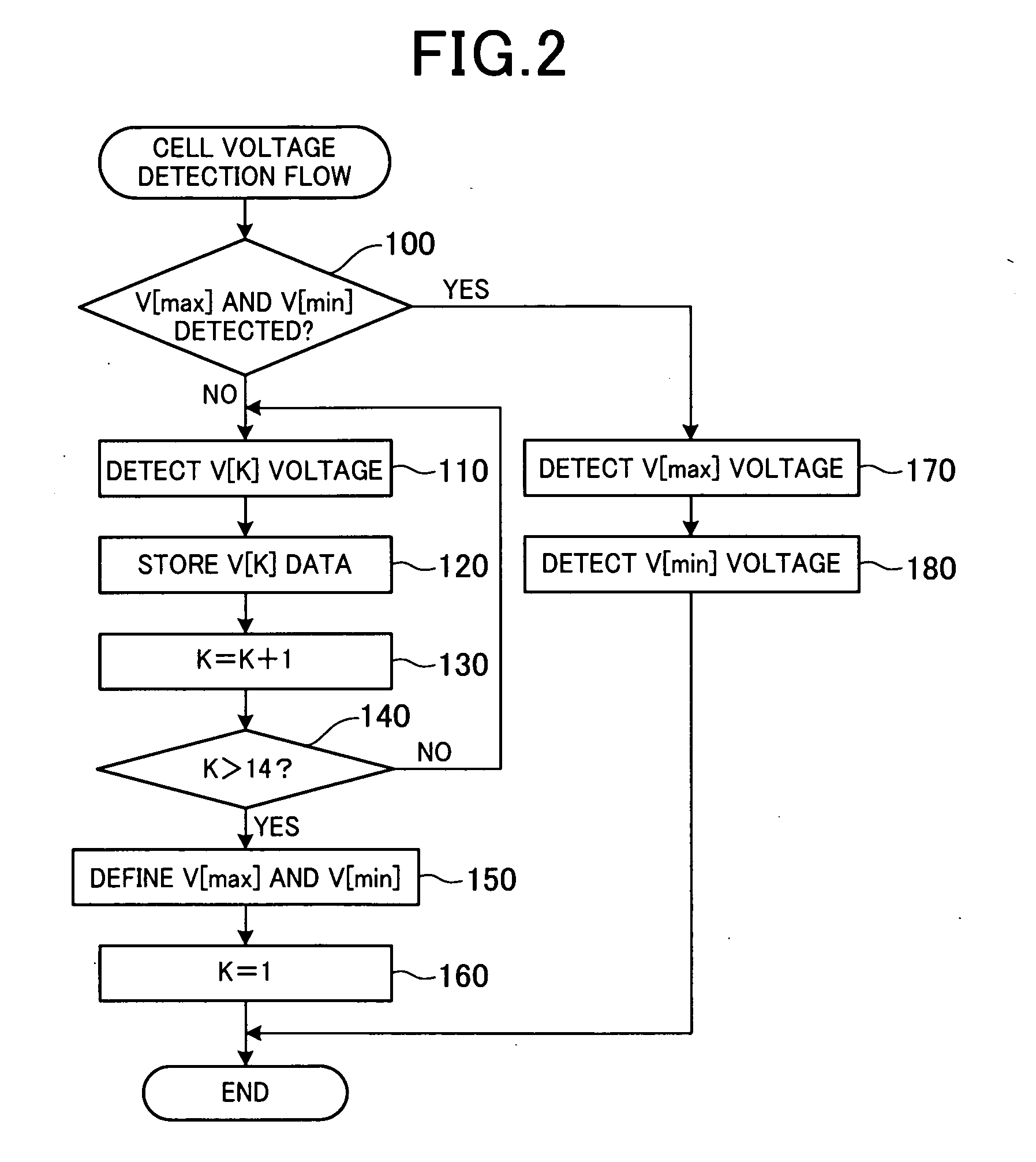
[0101]In the present embodiment, the cell-number generation circuit 94 is ensured to define the cell 11 having a highest cell voltage or the cell 11 having a lowest cell voltage from among the cells 11, based on the outputs from the comparators 81d to 83d. After that, the cell-number generation circuit 94 is ensured to output data that includes the information (cell-number information) for locating the defined cell voltage 11 to the microcomputer 70. Accordingly, as shown in FIG. 7A, the cell-numb...


PUM


Abstract

An apparatus is provided, which monitors an operation state of a battery composed of a plurality of cells mutually connected in series. In this apparatus, a cell voltage of each of the plurality of cells is detected as information indicating an operation state of the battery. Based on the detected cell voltages, an operation state is monitored for a cell having a highest cell voltage and a cell having a lowest cell voltage among the plurality of cells.

Description

CROSS REFERENCE TO RELATED APPLICATIONS[0001]This application is based on and claims the benefit of priority from earlier Japanese Patent Application No. 2010-233579 filed Oct. 18, 2010, the description of which is incorporated herein by reference.BACKGROUND OF THE INVENTION[0002]1. Technical Field[0003]The present invention relates to an apparatus for monitoring an operation state of a battery pack composed of a plurality of cells which are mutually connected in series, and in particular to an apparatus for monitoring an operation state of a battery pack by detecting the voltage of the plurality of cells.[0004]2. Related Art[0005]Recently, battery packs, as represented by lithium batteries, having a plurality of cells mutually connected in series are more frequently used. Usually, such a battery pack is used in combination with an apparatus for monitoring an operation state (e.g., presence / absence of a failure) of the plurality of cells (hereinafter referred to as “battery-state mo...

Claims


Application Information

Patent Timeline
IPC IPC(8): G01N27/416H02J7/00H02J7/02
CPCG01R19/16542G01R31/362G01R31/3658H01M10/482Y02T10/7055H02J7/0019H02J7/0021Y02E60/12H01M2010/4271G01R31/3835G01R31/396Y02E60/10Y02T10/70H02J7/0013H02J7/0016H02J7/0048
Inventor KOBAYASHI, TETSUYA
Owner DENSO CORP
Why Eureka
Try Eureka