Camera-shake correction device

a technology of camera-shake and correction device, which is applied in the direction of camera focusing arrangement, printers, instruments, etc., can solve the problems of complex structure, inconvenient miniaturization, and difficulty in applying a sensor-shifting type of camera-shake correction apparatus to a small camera, and achieves low profile and small size.

Inactive Publication Date: 2012-06-21
MITSUMI ELECTRIC CO LTD
View PDF2 Cites 348 Cited by
  • Summary
  • Abstract
  • Description
  • Claims
  • Application Information

AI Technical Summary

Benefits of technology

[0064]The present invention uses a permanent magnet of an auto-focusing lens drive apparatus in comm...

Problems solved by technology

Consequently, it is difficult to apply a sensor-shifting type of camera-shake correction apparatus to a small camera for mobile phone use from a size (external shape and height) standpoint.
Therefore, a problem with an image blurring correction apparatus (camera-shake correction apparatus) having such a structure is that its structure is complex and it is not suitable for miniaturization.
That is to say, as with an above-described sensor-shifting type of camera-shake correct...

Method used


Image

  • Camera-shake correction device
  • Camera-shake correction device
  • Camera-shake correction device

Examples


first embodiment

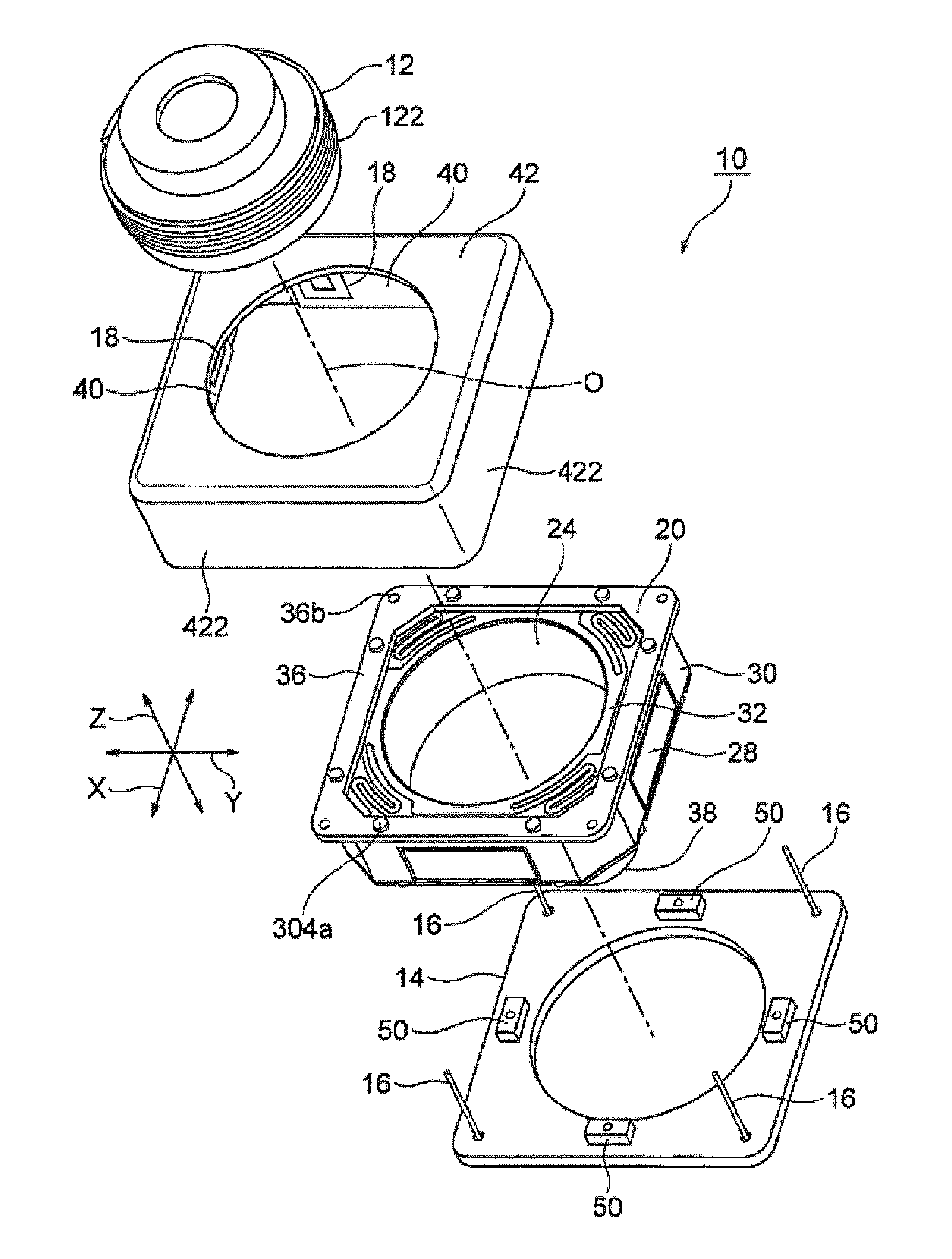
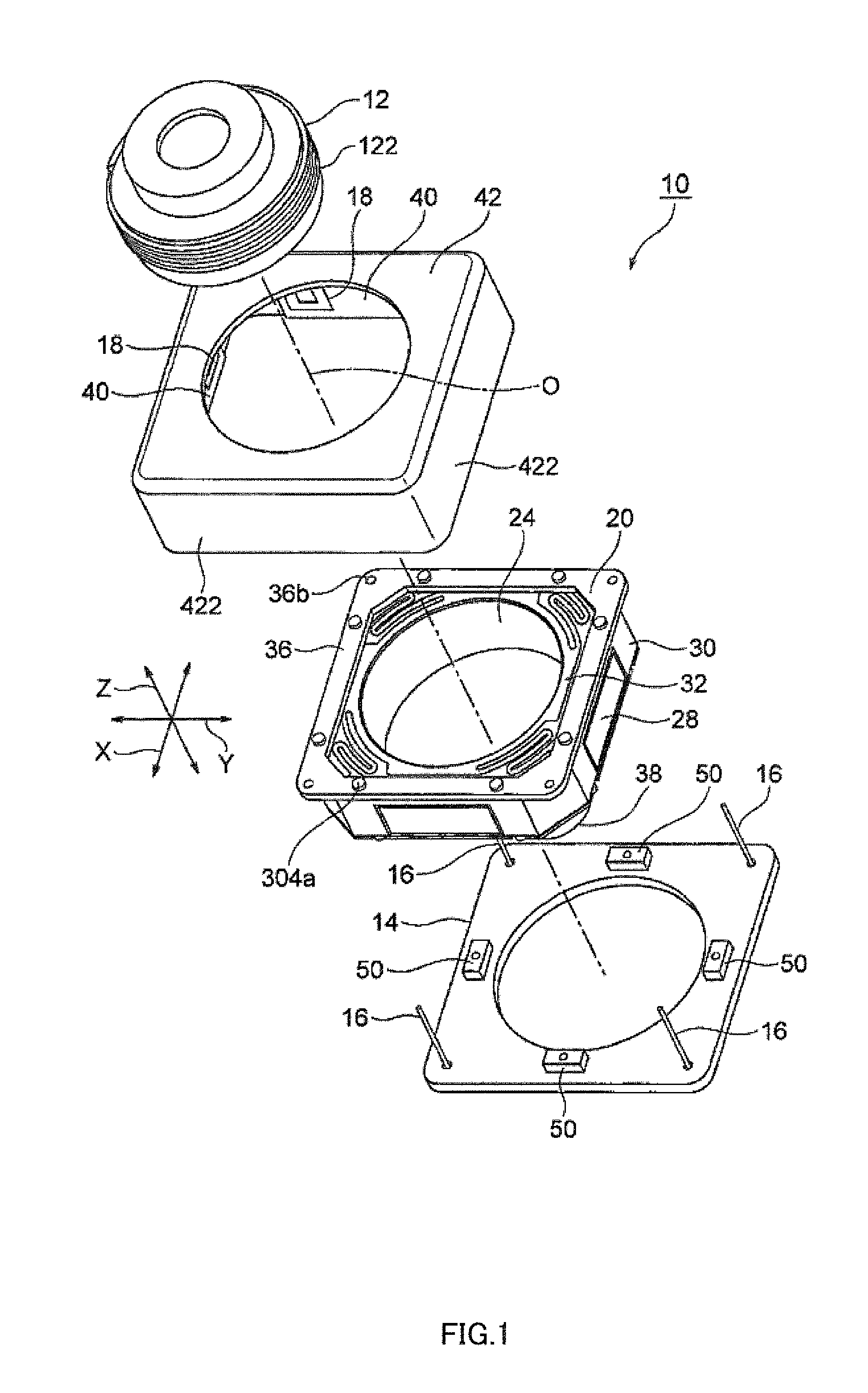
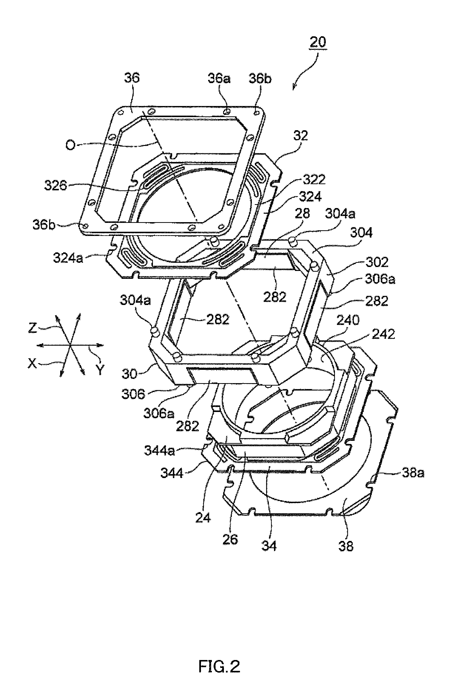
[0083]Camera-shake correction apparatus 10 according to the present invention will now be described with reference to FIG. 1 through FIG. 3. FIG. 1 is an exploded oblique view of camera-shake correction apparatus 10. FIG. 2 is an exploded oblique view of auto-focusing lens drive apparatus 20 used in camera-shake correction apparatus 10 shown in FIG. 1. FIG. 3 is an assembled oblique view, excluding shield cover 42, of camera-shake correction apparatus 10 shown in FIG. 1.

[0084]Here, orthogonal coordinate system (X,Y,Z) is used, as shown in FIG. 1 through FIG. 3. In the states illustrated in FIG. 1 through FIG. 3, in orthogonal coordinate system (X,Y,Z), the X-axis direction is the front-back direction (depth direction), the Y-axis direction is the horizontal direction (width direction), and the Z-axis direction is the vertical-direction (height direction). In the examples shown in FIG. 1 through FIG. 3, vertical direction Z is the lens optical axis O direction. In this first embodime...

second embodiment

[0130]Camera-shake correction apparatus 10A according to the present invention will now be described with reference to FIG. 5 through FIG. 8. FIG. 5 is an external oblique view of camera-shake correction apparatus 10A. FIG. 6 is a vertical cross-sectional view of camera-shake correction apparatus 10A. FIG. 7 is an exploded oblique view of camera-shake correction apparatus 10A. FIG. 8 is an exploded oblique view of auto-focusing lens drive apparatus 20A used in camera-shake correction apparatus 10A shown in FIG. 5.

[0131]Here, orthogonal coordinate system (X,Y,Z) is used, as shown in FIG. 5 through FIG. 8. In the states illustrated in FIG. 5 through FIG. 8, in orthogonal coordinate system (X,Y,Z), the X-axis direction is the front-back direction (depth direction), the Y-axis direction is the horizontal direction (width direction), and the Z-axis direction is the vertical-direction (height direction). In the examples shown in FIG. 5 through FIG. 8, vertical direction Z is the lens opti...

third embodiment

[0190]Camera-shake correction apparatus 10B according to the present invention will now be described with reference to FIG. 12 through FIG. 15. FIG. 12 is an external oblique view of camera-shake correction apparatus 10B. FIG. 13 is a vertical cross-sectional view of camera-shake correction apparatus 10B. FIG. 14 is an exploded oblique view of camera-shake correction apparatus 10B. FIG. 15 is an exploded oblique view of auto-focusing lens drive apparatus 20B used in camera-shake correction apparatus 10B shown in FIG. 12.

[0191]Here, orthogonal coordinate system (X,Y,Z) is used, as shown in FIG. 12 through FIG. 15. In the states illustrated in FIG. 12 through FIG. 15, in orthogonal coordinate system (X,Y,Z), the X-axis direction is the front-back direction (depth direction), the Y-axis direction is the horizontal direction (width direction), and the Z-axis direction is the vertical-direction (height direction). In the examples shown in FIG. 12 through FIG. 15, vertical direction Z is ...


PUM


Abstract

A small size, low profile camera-shake correction device. A camera-shake correction device (10) corrects camera shake by moving the entire auto-focusing lens drive device (20) in a first direction (X) and a second direction (Y) which are perpendicular to the optical axis (O) and are perpendicular to each other, the auto-focusing lens drive device (20) being provided with a focusing coil (26) and a permanent magnet (28) which is disposed on the outside of the focusing coil. The camera-shake correction device (10) includes: a base (14) disposed so as to be spaced from the bottom surface of the auto-focusing lens drive device (20); suspension wires (16) which each have one end affixed to the outer peripheral section of the base, which extend along the optical axis (O), and which support the entire auto-focusing lens drive device (20) in such a manner that the auto-focusing lens drive device (20) is rockable in the first direction (X) and the second direction (Y); and a camera-shake correcting coil (18) disposed so as to face the permanent magnet (28).

Description

TECHNICAL FIELD[0001]The present invention relates to a camera-shake correction apparatus. and more particularly to a camera-shake correction apparatus that corrects camera shake (vibration) that occurs when a still image is captured with a small camera for mobile phone use, and enables a blur-free image to be captured.BACKGROUND ART[0002]Various camera-shake correction apparatuses (image blurring correction apparatuses) have hitherto been proposed that enable blurring on an imaging surface to be prevented and sharp imaging to be achieved despite the occurrence of camera shake (vibration) when a still image is captured.[0003]Optical methods such as a sensor shifting method and lens shifting method, and software methods in which camera shake is corrected by image processing by means of software, are known as camera-shake correction methods.[0004]A sensor shifting method is disclosed in Patent 2004-274242 (Patent Literature 1), for example. A digital camera disclosed in Patent Literat...

Claims


Application Information

Patent Timeline
IPC IPC(8): H04N5/228G03B13/36
CPCG03B3/10G03B5/00G03B2205/0015H04N5/23248H04N5/2254H04N5/2257G03B2205/0069G02B7/08G02B27/646G02B7/09G03B5/06G03B13/36H04N23/57H04N23/55H04N23/68H04N23/685H04N23/687H04N23/54H04N23/682H04N25/00G03B3/00G03B17/02G03B17/00G02B13/001
Inventor MORIYA, AKIHIROSUGAWARA, MASAYOSHI
Owner MITSUMI ELECTRIC CO LTD
Why Eureka
Try Eureka