
Bi-polar ionization tube base and tube socket

a technology of ionization tube and tube socket, which is applied in the direction of electrostatic separation, electrostatic charge, chemistry apparatus and processes, etc., can solve the problems of exposed grounding strap b>19/b> and ineffective microorganisms

Inactive Publication Date: 2012-06-21
BIOCLIMATIC AIR SYST
View PDF7 Cites 22 Cited by
  • Summary
  • Abstract
  • Description
  • Claims
  • Application Information

AI Technical Summary

Benefits of technology

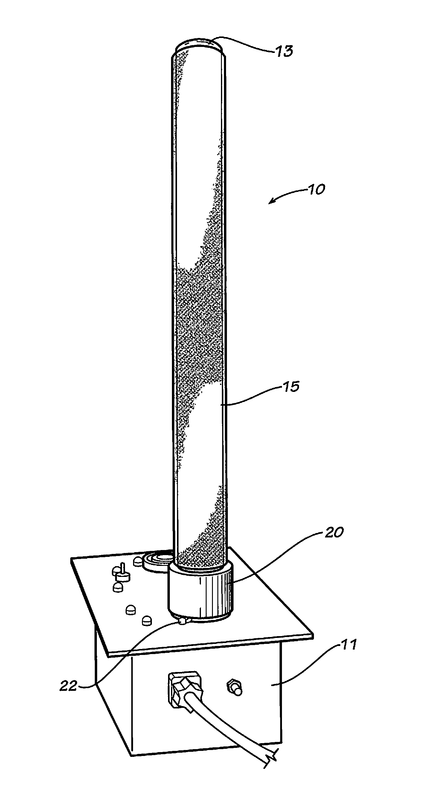
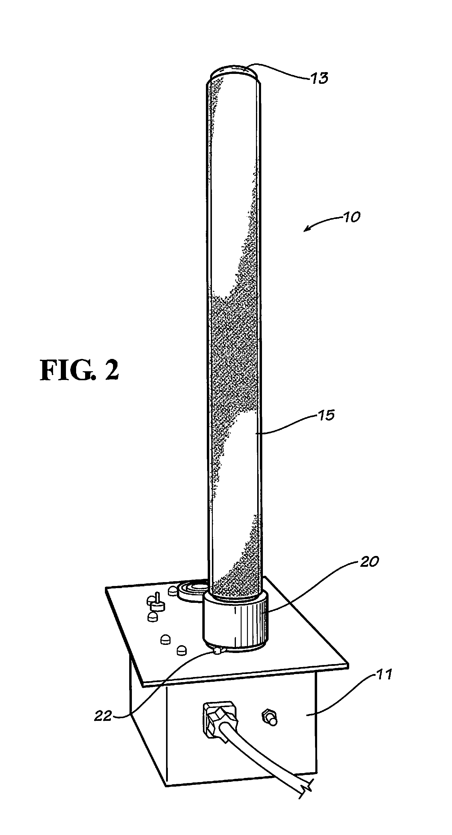
[0016]FIG. 2 shows a side view of the bi-polar ionization device with tube base a

Problems solved by technology

Microbial contaminants (mold, fungal spores, and bacteria) are controlled by exposure of the microbe to the ionization field, which will, after a suitable exposure alter the DNA and render the microbe ineffective.
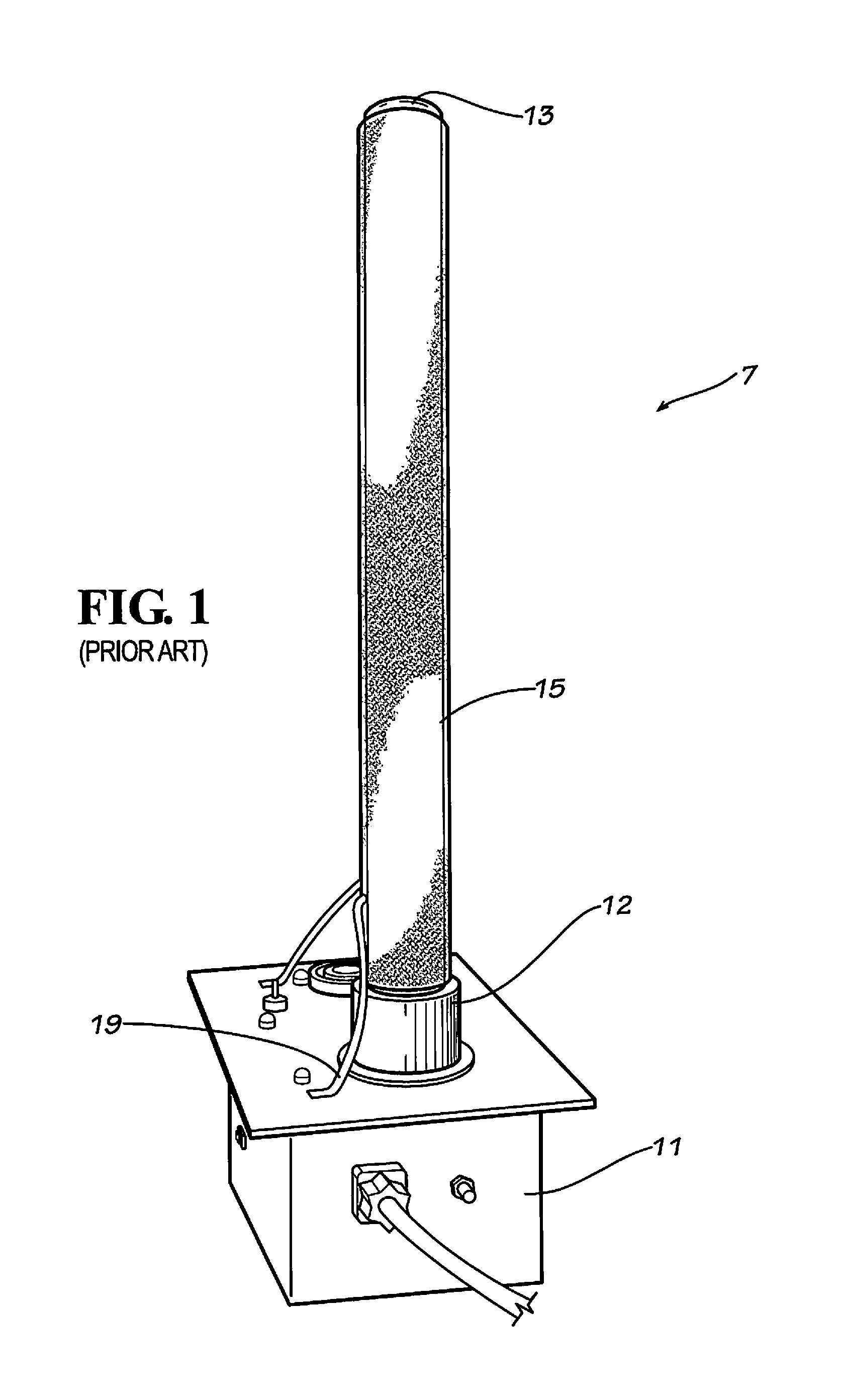
In doing so, the exposed grounding strap 19 present a shock hazard should the person forget to power down the unit when they tried to remove the outer electrical array 15 from the glass tube 13.

Method used


Image

  • Bi-polar ionization tube base and tube socket
  • Bi-polar ionization tube base and tube socket
  • Bi-polar ionization tube base and tube socket

Examples


Embodiment Construction

[0025]The present invention may be understood more readily by reference to the following detailed description of the invention taken in connection with the accompanying drawing figures, which form a part of this disclosure. It is to be understood that this invention is not limited to the specific devices, methods, conditions or parameters described and / or shown herein, and that the terminology used herein is for the purpose of describing particular embodiments by way of example only and is not intended to be limiting of the claimed invention. Any and all patents and other publications identified in this specification are incorporated by reference as though fully set forth herein.

[0026]Also, as used in the specification including the appended claims, the singular forms “a,”“an,” and “the” include the plural, and reference to a particular numerical value includes at least that particular value, unless the context clearly dictates otherwise. Ranges may be expressed herein as from “abou...


PUM


Abstract

The present invention provides an air treatment apparatus. The air treatment apparatus comprises a housing electrically connectable to a voltage source and generating a high voltage and a glass tube. The air treatment apparatus further comprises a tube base electrically connecting internally high voltage to an inner electrode within the glass tube and electrically connected internally an outer electrode surrounding the glass tube and a tube socket electrically connected internally to the outer electrode and electrically connected to a grounding pad, wherein the grounding pad is mechanically connectable to the housing and electrically connectable to the housing.

Description

CROSS-REFERENCE TO RELATED APPLICATIONS[0001]This application is a continuation of International Application No. PCT / US2009 / 051998 filed on Jul. 28, 2009, which claims the benefit of U.S. Provisional Patent Application Ser. No. 61 / 083,999 filed on Jul. 28, 2008, the entireties of which are hereby incorporated herein by reference for all purposes.FIELD OF THE INVENTION[0002]The present invention relates to a bi-polar ionization tube base and tube socket. The invention is comprised of a socket high voltage insert, ground spring insert and housing incorporates the tube socket assembly that attaches to the glass tube / wire mesh assembly. The ground spring and housing incorporates the tube base assembly. The connection of tube socket to tube base creates an electrical circuit to produce ionization thru the tube.DESCRIPTION OF BACKGROUND[0003]Currently, bi-polar ionization represents a proven technology for the generation of an alternating current ionization field. Bioclimatic is a “Non-th...

Claims


Application Information

Patent Timeline
IPC IPC(8): H01T23/00
CPCB03C3/383B03C3/86B03C3/41
Inventor VAYNERMAN, TAISAORLOV, NIKOLAYZITIN, STEPHEN
Owner BIOCLIMATIC AIR SYST
Learn More