Multi-layer armature for moving armature receiver

a technology of moving armatures and receivers, which is applied in the direction of electrical devices, dynamo-electric machines, electrical transducers, etc., can solve the problem that the armature does not provide a significant improvement in the maximum deflection of the armatur

Active Publication Date: 2012-06-21
SONION NEDERLAND
View PDF2 Cites 90 Cited by
  • Summary
  • Abstract
  • Description
  • Claims
  • Application Information

AI Technical Summary

Benefits of technology

[0019]The armature layers may have substantially identical thicknesses in some embodiments of the present multi-layer armature or different thicknesses in other embodiments of the invention. If the layer thickness is different, each of the outermost layers is preferably thinner than the inner or middle layer or layers. The outermost layers may also be shorter than the inner / middle layer or layers so that a distant portion of a deflectable armature leg consists of a single armature layer only. This reduces a moving mass of the distant portion of the deflectable armature leg without any noticeable penalty in overall magnetic reluctance of the multi-layer armature since magnetic reluctance in the region close to the drive coil is of primary importance. The thickness of each of the first and second armature layers preferably lies between 25 μm and 200 μm. A third or further armature layers may have similar thicknesses.

Problems solved by technology

Thus, merely increasing the cross-sectional area of the armature does not provide a significant improvement in the maximum deflection of the armature.

Method used


Image

  • Multi-layer armature for moving armature receiver
  • Multi-layer armature for moving armature receiver
  • Multi-layer armature for moving armature receiver

Examples


second embodiment

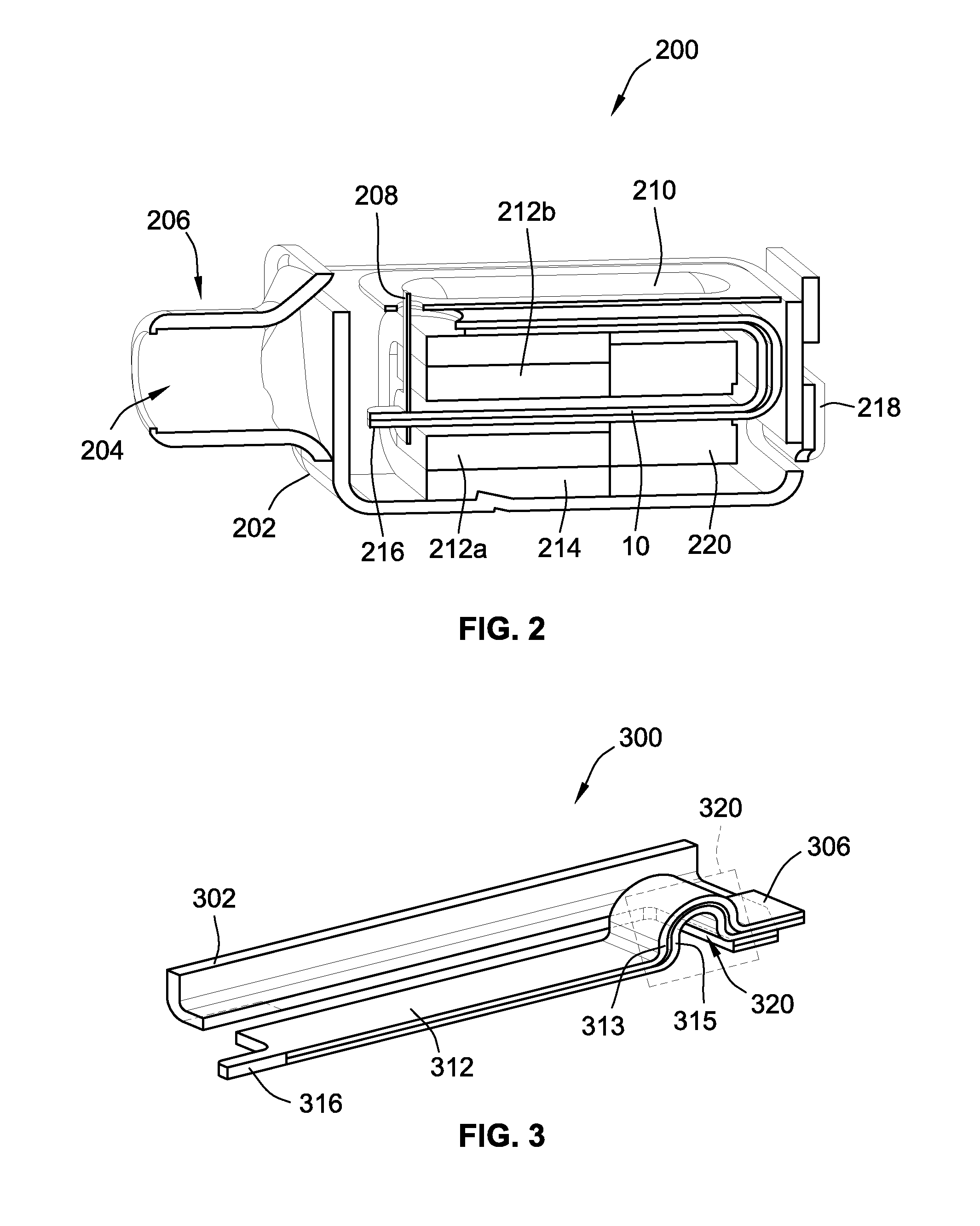
[0038]FIG. 3 is a partial cross-sectional view of an E-shaped armature 300 in accordance with the invention. A residual portion of the E-shaped armature 300 may have a shape similar to the shape of E-shaped armature depicted on FIG. 4.

[0039]The E-shaped armature 300 comprises a flat elongate armature leg 312 forming a middle or central leg of an E-shaped armature outline. A flat and bent first outer leg 302 extends substantially parallelly with the flat elongate armature leg 312 while a symmetrically positioned and similarly shaped second outer leg has been left out of the illustration for simplicity. The flat elongate armature leg 312 is deflectable relative to a stationary portion of the E-shaped armature and comprises a narrowed distal leg portion 316 that may be used as attachment point for a drive pin or rod. A proximate leg portion 306 is mechanically and magnetically attached to a shared coupling leg or keeper. The shared coupling leg functions to mechanically and magneticall...

third embodiment

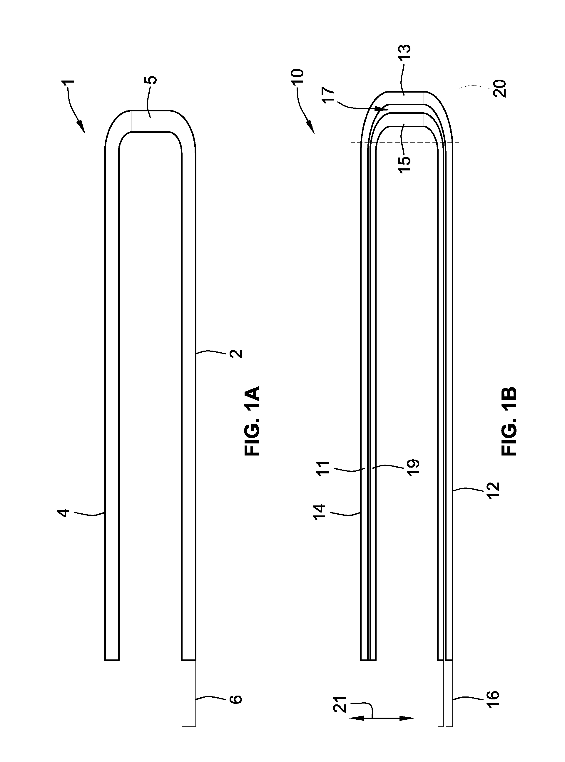
[0041]FIGS. 4a) and 4b) illustrate a perspective view and a cross-sectional view, respectively, of an E-shaped armature in accordance with the invention. As illustrated in FIG. 4a), the E-shaped armature 400 comprises a first or upper armature layer 413 positioned adjacently to a second or lower armature layer 415. Respective surfaces of the upper and lower armature layers are placed adjacently to each other only separated by a thin intermediate layer or gap 417. As illustrated, the displacement region extends between the first and second armature layers 413, 415 throughout the entirety of their adjacent surface areas as opposed to the embodiment disclosed above in connection with FIG. 3 where the displacement region 320 is limited to a certain sub-section of the E-shape armature 300.

[0042]Each of the upper and lower armature layers 413, 415 furthermore comprises a pair of bent upwardly or downwardly extending flaps or elbows 420, 421, respectively. The flaps 420, 421 form part of a...


PUM


Abstract

A multi-layer armature for a moving armature receiver. The armature includes a first armature layer and a displacement region. The first armature layer includes a first surface and a second armature layer having a second surface positioned adjacent to the first surface. The displacement region provides relative displacement between the armature layers. The multi-layer construction of the armature in combination with the displacement region creates considerable design freedom in choosing armature geometry outside conventional bounds posed by the above-mentioned constraint between armature cross-sectional area and its mechanical stiffness. The design freedom can be applied to achieve numerous performance benefits for the moving armature receiver such as higher electroacoustic conversion efficiency, increased maximum sound pressure output or smaller overall length of the multi-layer armature. The smaller length leads to a smaller size of moving armature receivers which is an important performance metric for moving armature receivers for numerous severely size-constrained applications.

Description

CROSS-REFERENCE TO RELATED APPLICATIONS[0001]This application claims the benefit of U.S. Provisional Patent Application Ser. No. 61 / 422,920, filed Dec. 14, 2010, and titled “Multi-Layer Armature for Moving Armature Receiver,” which is incorporated herein by reference in its entirety.FIELD OF THE INVENTION[0002]The present invention relates to armatures for moving armature receivers such as miniature balanced armature receivers for portable communication devices. More specifically, the invention relates to a multi-layer armature for a moving armature receiver comprising a first armature layer comprising a first surface and a second armature layer comprising a second surface positioned adjacently to the first surface. A displacement region of the multi-layer armature is configured to provide relative displacement between the first and second armature layers in a predetermined direction.BACKGROUND OF THE INVENTION[0003]Moving armature receivers are widely used to convert electrical aud...

Claims


Application Information

Patent Timeline
Patent Type & Authority Applications(United States)
IPC IPC(8): H04R1/00H02K41/035
CPCH04R11/02
Inventor REEUWIJK, SIETSE JACOB VANBROUWER, THEODORUS GERADUS MARIALAFORT, ADRIANUS MARIAKORNEEV, MIKHAIL JOERJEVITSJ
Owner SONION NEDERLAND
Why Eureka
Try Eureka