
Manufacturing-process equipment

Inactive Publication Date: 2012-06-21
NAT FORMOSA UNIV
View PDF38 Cites 10 Cited by
  • Summary
  • Abstract
  • Description
  • Claims
  • Application Information

AI Technical Summary

Benefits of technology

[0008]The main objective of the present invention is to provide a manufacturing-process equipment, and more particularly to a manufacturing-process equipment that can be used to form nanometer structure pattern accurately and quickly on the workpieces.

Problems solved by technology

However, the working speed of the above-mentioned conventional lithography technologies is slow and the equipment or equipments for the conventional lithography technologies are expensive.
When the length of the optics ruler is longer than 1 meter, the working error will increase and this will influence the detecting result.
Therefore, the precision of the conventional long-stroke moving stage cannot reach the nanometer level.
The movement of the conventional multi-axle short-travel moving platform is about hundred micrometers, and this cannot form a large range of nanometer structure pattern or nanometer holes in the workpieces.

Method used


Image

  • Manufacturing-process equipment
  • Manufacturing-process equipment
  • Manufacturing-process equipment

Examples


Embodiment Construction

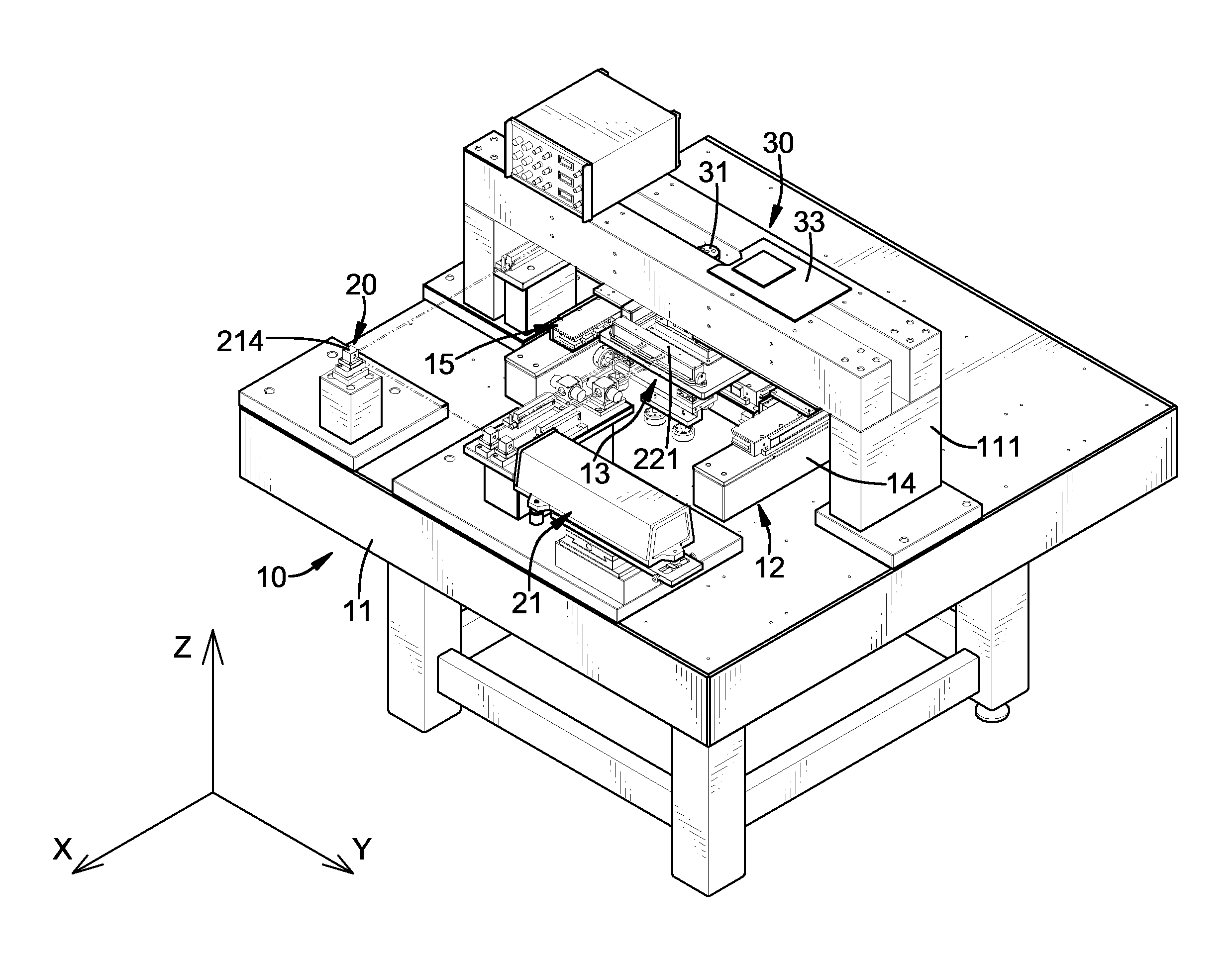
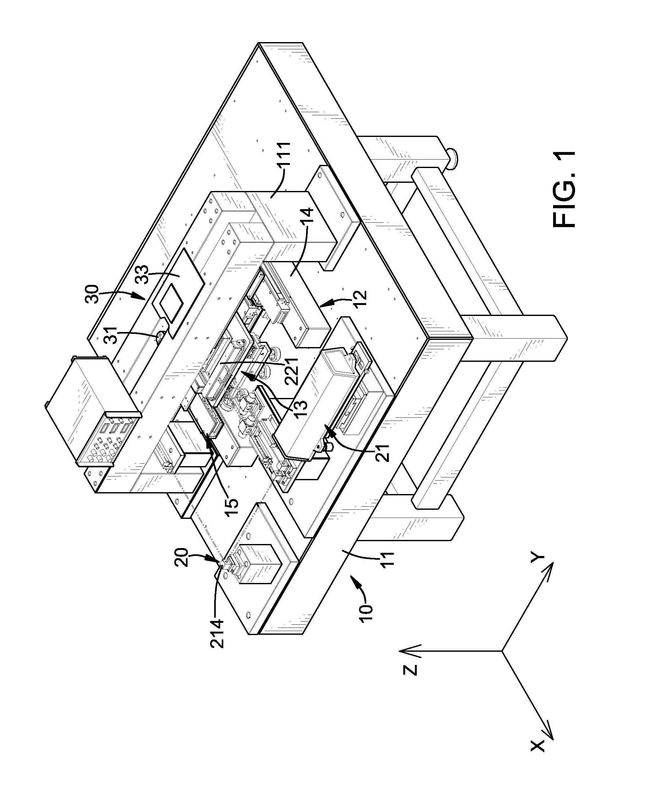
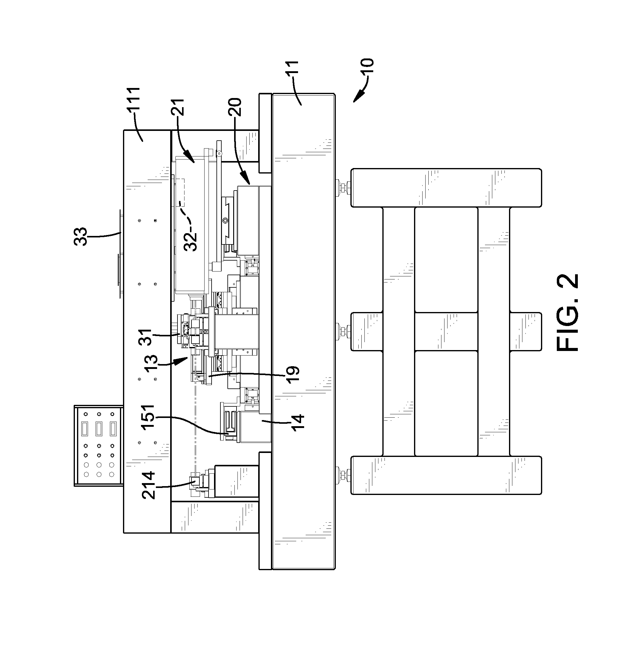
[0017]With reference to FIGS. 1 to 4, a manufacturing-process equipment in accordance with the present invention comprises a platform assembly 10, a measurement feedback assembly 20 and a laser-working assembly 30.

[0018]The platform assembly 10 has a base 11 and a hybrid-moving platform. The base 11 has a top and a mounting frame 111. The mounting frame 111 may be inversed U-shaped and is mounted on the top of the base 11 at the middle and has a top and a bottom.

[0019]The hybrid-moving platform is mounted on the top of the base 11 below the mounting frame 111 and has a long-stroke moving stage 12 and a piezo-driven micro-stage 13.

[0020]The long-stroke moving stage 12 is mounted on the top of the base 11 below the mounting frame 111 and has a benchmark set 14 and a driving device 15. The benchmark set 14 is H-shaped, is mounted securely on the top of the base 11 and may be made of granite. The thermal expansion coefficient of granite is low and the grinding precision can reach 2 micr...


PUM

PropertyMeasurementUnit
Angleaaaaaaaaaa

Abstract

A manufacturing-process equipment has a platform assembly, a measurement feedback assembly and a laser-working assembly. The platform assembly has a base and a hybrid-moving platform. The base has a mounting frame. The hybrid-moving platform is mounted on the base and has a long-stroke moving stage and a piezo-driven micro-stage. The long-stroke moving stage has a benchmark set and a driving device. The piezo-driven micro-stage is connected to the long-stroke moving stage and has a working platform. The measurement feedback assembly is securely mounted on the platform assembly and has a laser interferometer, a reflecting device and a signal-receiving device. The laser-working assembly is mounted on the platform assembly, is electrically connected to the measurement feedback assembly and has a laser direct-writing head, a controlling interface device and a positioning interface device.

Description

BACKGROUND OF THE INVENTION[0001]1. Field of the Invention[0002]The present invention relates to a manufacturing-process equipment for a workpieces, and more particularly to a manufacturing-process equipment that can be used to form nanometer structure pattern accurately and quickly on the workpieces.[0003]2. Description of the Prior Arts[0004]In general, conventional lithography technologies that used to form nanometer structure pattern or nanometer holes on a workpieces include photolithography process, electron beam lithography technology, laser interference lithography technology and laser exposure lithography technology.[0005]However, the working speed of the above-mentioned conventional lithography technologies is slow and the equipment or equipments for the conventional lithography technologies are expensive. Additionally, the design of the platform, the precision of the position of the platform, the optical positioning system and the temperature control will influence the wo...

Claims


Application Information

Patent Timeline
IPC IPC(8): B29C59/16B29C37/00
CPCB23K26/0853
Inventor JYWE, WEN-YUHSHEN, JING-CHUNGYANG, CHIN-TIENLIU, CHIEN-HUNGJU, JAU-JIUWU, CHIA-HUNGHUANG, CHUN-CHIEHDUAN, LILILEE, YUAN-CHIN
Owner NAT FORMOSA UNIV
Learn More