
Method for fabricating semiconductor device

Inactive Publication Date: 2007-12-06
PANASONIC CORP
View PDF2 Cites 7 Cited by
  • Summary
  • Abstract
  • Description
  • Claims
  • Application Information

AI Technical Summary

Benefits of technology

[0014] An object of the present invention is to solve the conventional problems described above, and to provide a method for fabricating a semiconductor device capable of accurately forming a fully silicided gate electrode with a predetermined silicide composition.
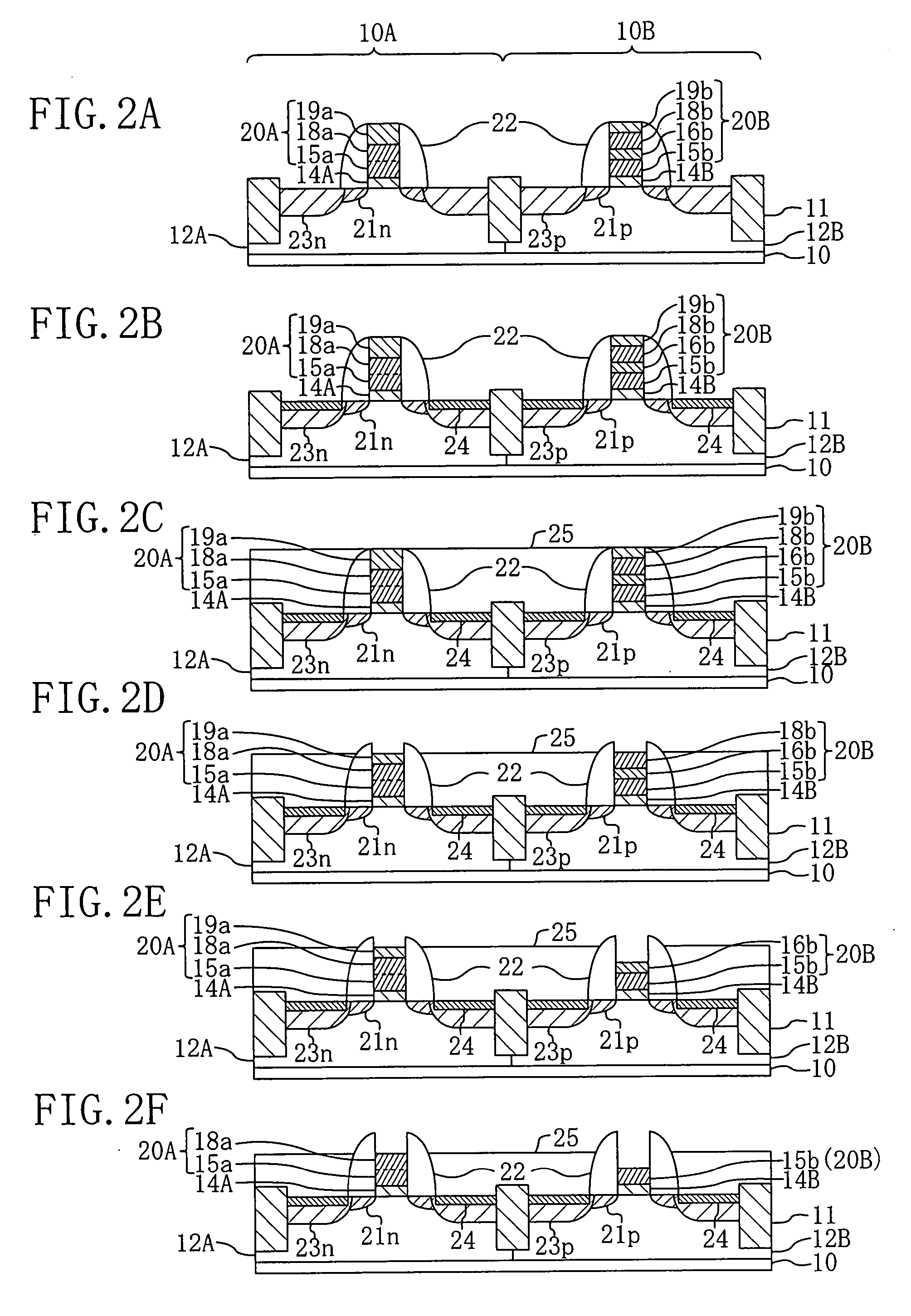
[0017] With the method for fabricating a semiconductor device according to the present invention, in the second-gate-electrode formation portion, only the second silicon film can be selectively removed therefrom, and full silicidation is conducted on the first silicon film. On the other hand, in the first-gate-electrode formation portion, full silicidation is conducted on the first and second silicon films. Therefore, two types of fully silicided gate electrodes having different silicide compositions can be formed with a good repeatability.
[0023] Preferably, in the above case, the step (c1) is the step of forming, over the first region, a mask film covering the first-gate-electrode formation portion, and then selectively removing, using the mask film as an etching mask, the second protective film of the second-gate-electrode formation portion to expose the second silicon film. With this method, the second protective film can be allowed to remain reliably in the first-gate-electrode formation portion, so that etching of the second silicon film can be reliably blocked in the first-gate-electrode formation portion.
[0025] Preferably, in the method for fabricating a semiconductor device according to the present invention, the step (c) includes: the step (c1) of removing the second protective film of the first-gate-electrode formation portion to expose the second silicon film, and removing the second protective film of the second-gate-electrode formation portion to expose the second silicon film; the step (c2) of forming, after the step (c1), a mask film over the first region, the mask film covering the second silicon film of the first-gate-electrode formation portion; and the step (c3) of selectively etching, using the mask film as an etching mask, the second silicon film and the first protective film of the second-gate-electrode formation portion to expose the first silicon film. With this method, the first protective film does not have to be allowed to remain in the first-gate-electrode formation portion. Therefore, the first-protective-film etching step can be simplified.

Problems solved by technology

However, only replacement of a polysilicon gate electrode of a transistor with a FUSI gate electrode will rather cause a change in the threshold voltage of the transistor due to the work functions of the gate electrodes.
This makes it difficult for each of a p-channel MIS (metal-insulator-semiconductor) transistor and an n-channel MIS transistor to secure a predetermined threshold voltage.
The conventional method for forming a fully silicided gate electrode, however, has a problem that since the thickness of the polysilicon film is adjusted by etching, the adjusted film thickness widely varies.
This leads to variation in threshold voltage and gate resistance.

Method used


Image

  • Method for fabricating semiconductor device
  • Method for fabricating semiconductor device
  • Method for fabricating semiconductor device

Examples


Embodiment Construction

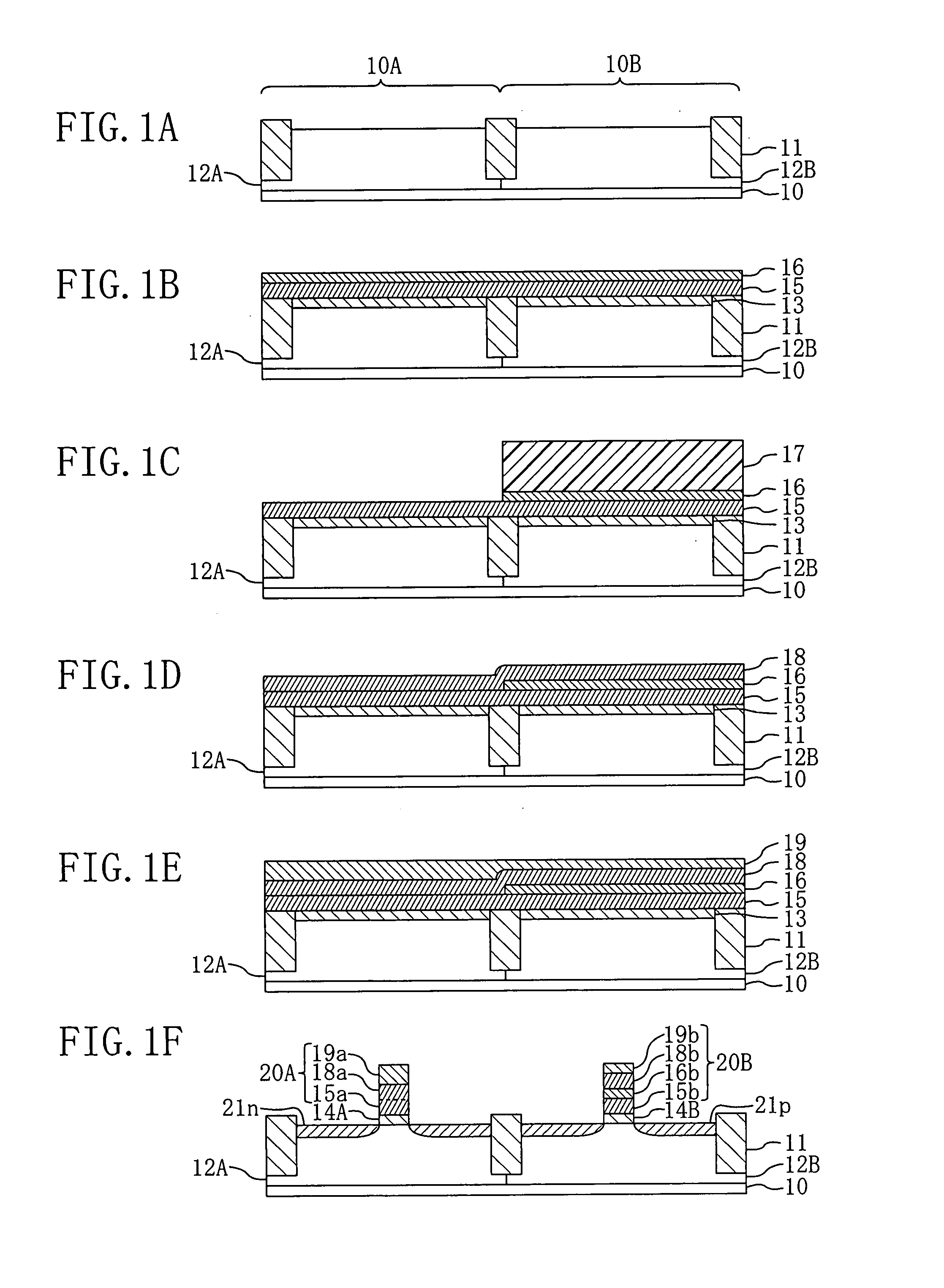
[0037] One embodiment of the present invention will be described with reference to the accompanying drawings. FIGS. 1 to 3 show cross-sectional structures of successive fabrication process steps of a method for fabricating a semiconductor device according to one embodiment. In this embodiment, description will be made of a method for fabricating n- and p-type MIS transistors in first and second regions 10A and 10B, respectively.

[0038] Referring to FIG. 1A, first, on a semiconductor substrate 10 made of, for example, p-type silicon, an isolation region 11 for electrically isolating elements is provided by an STI (shallow trench isolation) method or the like to form the first region 10A and the second region 10B. Then, by a lithography method and an ion implantation method, a p-type first well 12A and an n-type second well 12B are formed in the upper portion of the first region 10A and the second region 10B, respectively.

[0039] Next, as shown in FIG. 1B, in a region of the main surf...


PUM


Abstract

In a method for fabricating a semiconductor device, a first region in a semiconductor substrate is formed with a first-gate-electrode formation portion composed of a first silicon film, a second silicon film, and a second protective film, and a second region therein is formed with a second-gate-electrode formation portion composed of the first silicon film, a first protective film, the second silicon film, and the second protective film. Then, the first-gate-electrode formation portion is formed into a first fully silicided gate electrode, and the second-gate-electrode formation portion is formed into a second fully silicided gate electrode.

Description

CROSS-REFERENCE TO RELATED APPLICATIONS [0001] This application claims priority under 35 U.S.C. § 119 on Patent Application No. 2006-111001 filed in Japan on Apr. 13, 2006, the entire contents of which are hereby incorporated by reference. BACKGROUND OF THE INVENTION [0002] (a) Fields of the Invention [0003] The present invention relates to methods for fabricating a semiconductor device, and in particular to methods for fabricating a semiconductor device with fully silicided gate electrodes. [0004] (b) Description of Related Art [0005] With recent enhancement of packing density, functionality, and speed of a semiconductor integrated circuit device, a metal gate electrode thereof using a metal material is actively developed. Potential metal gate electrodes to be developed include: a dual metal gate electrode formed of a combination of two types of metal materials with different work functions; and a fully silicided (FUSI) gate electrode the whole of which is formed of metal silicide....

Claims


Application Information

Patent Timeline
IPC IPC(8): H01L21/336
CPCH01L21/28097H01L21/823835H01L29/7833H01L29/66545H01L29/6659H01L29/4975
Inventor SATO, YOSHIHIRO
Owner PANASONIC CORP
Learn More