
Nanowire transistor and method for fabricating the same

a technology of nanowire transistor and fabrication method, which is applied in the direction of basic electric elements, electrical apparatus, and semiconductor devices, can solve the problems of increased interface levels, too low breakdown voltage to achieve high reliability as a gate, and flexible substrate softening at a lower temperature, so as to achieve good stability, improve property, and improve reliability

Active Publication Date: 2012-06-21
JOLED INC
View PDF3 Cites 21 Cited by
  • Summary
  • Abstract
  • Description
  • Claims
  • Application Information

AI Technical Summary

Benefits of technology

[0033]The nanowire transistor of the present invention uses a nanowire with a core-shell structure, which has been formed separately from the substrate that supports the transistor. In addition, the shell portion is made of an insulator that can achieve high reliability as a gate insulating film. Particularly, according to the present invention, although the core portion is made of a single crystalline semiconductor, a cross section thereof that intersects with the longitudinal axis thereof has a curved profile. Consequently, the interface between the gate insulating film and the semiconductor core portion has an improved property. Besides, no matter where the nanowire is arranged with respect to the gate electrode, a conductive channel is always formed in the core portion with good stability. As a result, the reliability of the transistor improves.
[0034]A method for fabricating a nanowire transistor according to the present invention makes it possible to form a gate insulating film of quality without being restricted by the softening temperature of a flexible substrate. As a result, nanowire transistors with a reduced variation in performance can be integrated together on the flexible substrate.

Problems solved by technology

However, such a flexible substrate softens at a lower temperature than a glass substrate.
However, the organic insulating film and the inorganic insulating film, deposited at a low temperature, have too low breakdown voltages to achieve high reliability as a gate insulating film.
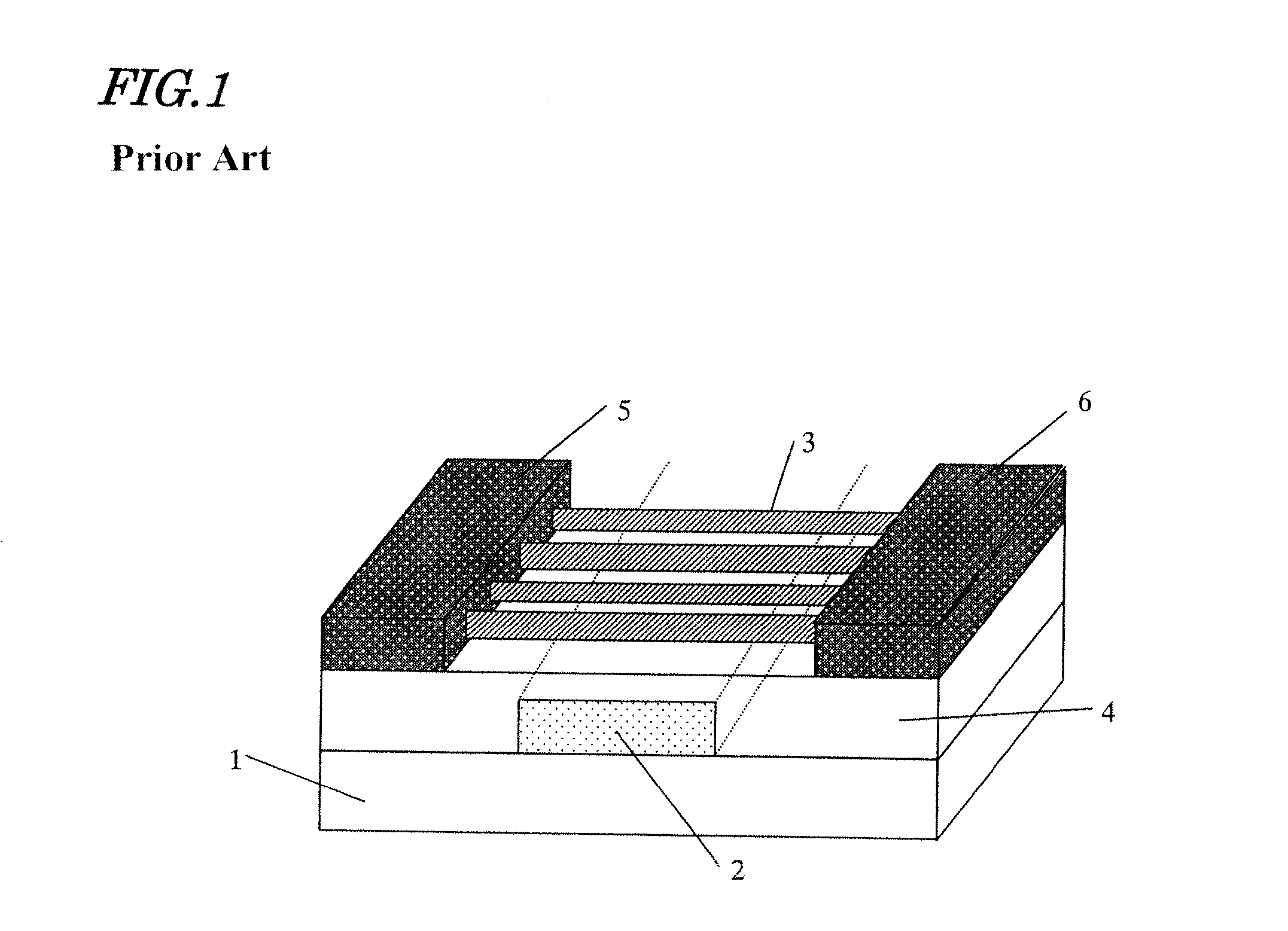
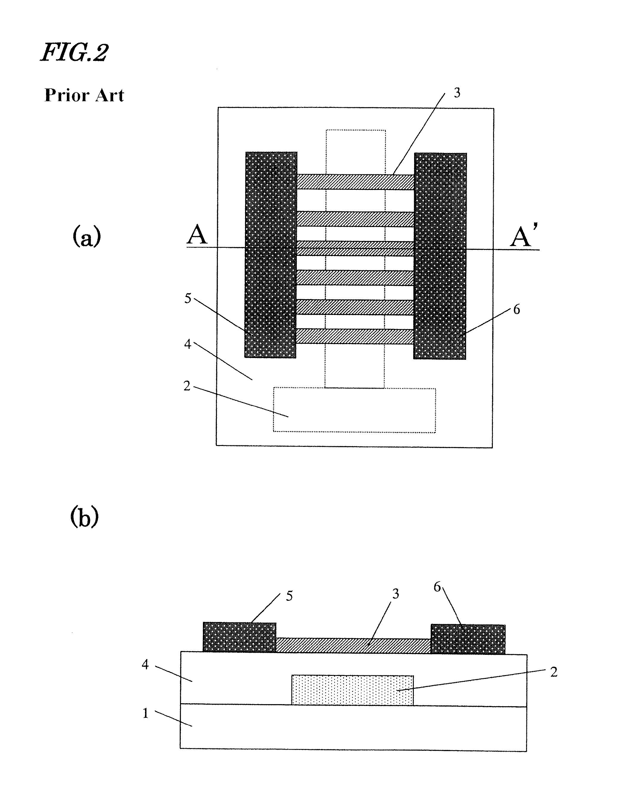
On top of that, the gate insulating film 4 formed by such a low-temperature process has increased interface levels and decreased carrier mobility in the interface between the film 4 and the channel, which is also a problem.
Besides, as there are fixed charges and mobile ions in the organic insulating film, the threshold value may shift, the current-voltage characteristic may produce hysteresis, and the variation in characteristic may increase.

Method used


Image

  • Nanowire transistor and method for fabricating the same
  • Nanowire transistor and method for fabricating the same
  • Nanowire transistor and method for fabricating the same

Examples


embodiment 1

[0062]Hereinafter, a first preferred embodiment of a nanowire transistor according to the present invention will be described.

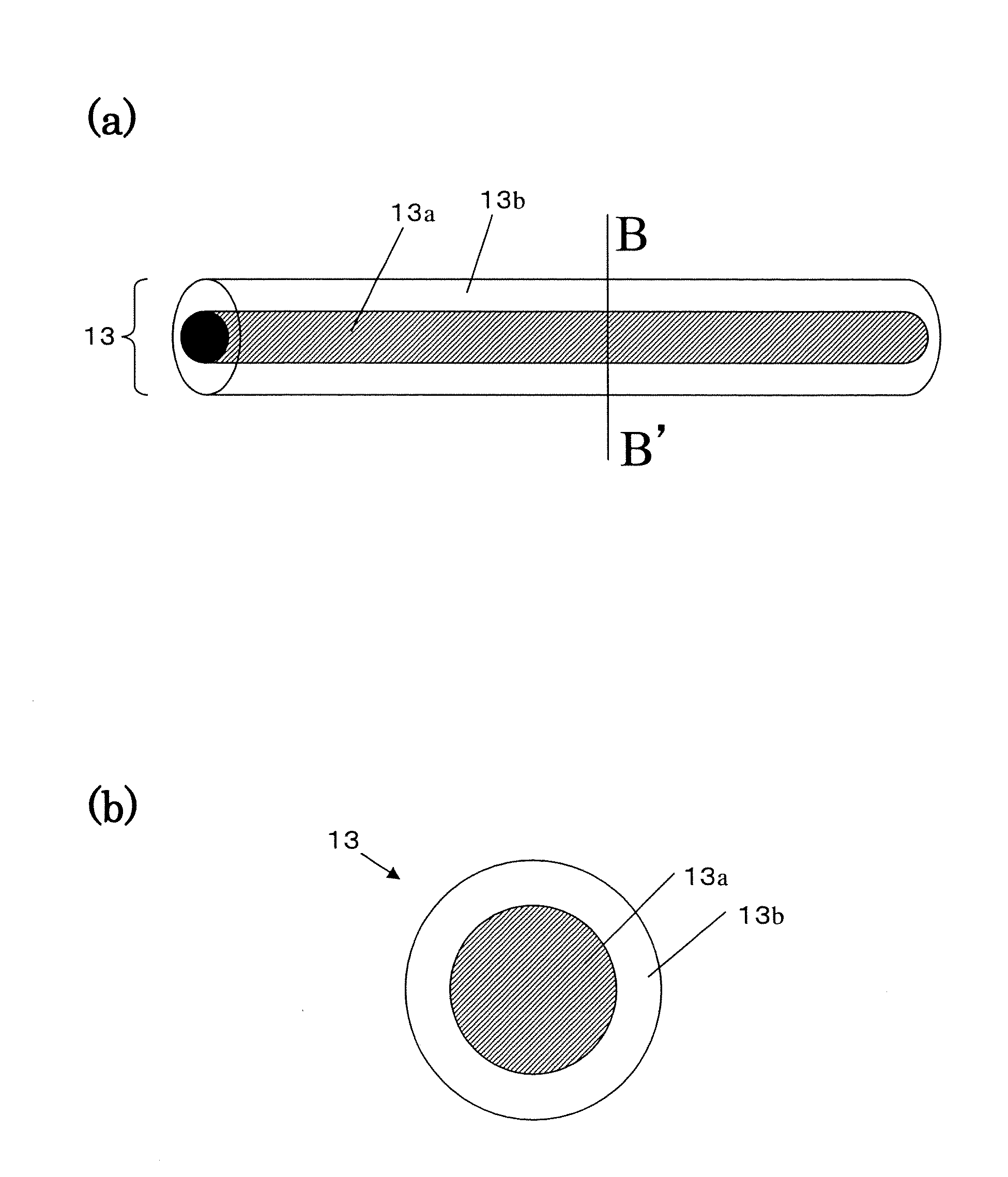
[0063]First, an example of a core-shell nanowire for use in the nanowire transistor of this preferred embodiment will be described with reference to FIGS. 3(a) and 3(b), which are a perspective view of a core-shell nanowire 13 and a cross-sectional view thereof as viewed on the plane B-B′ shown in FIG. 3(a).

[0064]As shown in FIG. 3, the core-shell nanowire 13 includes a semiconductor core portion 13a and an insulating shell portion 13b that coats the core portion 13a. The semiconductor core portion 13a is made of a Group V semiconductor including Si such as Si or SiGe. On the other hand, the insulating shell portion 13b is made of an insulator such as silicon dioxide or silicon oxynitride.

[0065]The core-shell nanowire 13 has a length of about 1 μm to about 100 μm. The semiconductor core portion 13a may have a diameter of about 2 nm to about 1 μm, preferably a...

embodiment 2

[0096]Hereinafter, a second preferred embodiment of a nanowire transistor according to the present invention will be described with reference to FIGS. 8(a) and 8(b), which are a top view schematically illustrating the configuration of a nanowire transistor according to this preferred embodiment and a cross-sectional view thereof as viewed on the plane D-D′.

[0097]The nanowire transistor of this preferred embodiment is quite different from the counterpart of the first preferred embodiment in that the gate electrode 12 has a number of grooves 20 in which the core-shell nanowires 13 are arranged as shown in FIG. 8.

[0098]The grooves 20 do not have to have a rectangular cross section but may also have a V- or U-cross section as shown in FIGS. 9(a) and 9(b). Although a single core-shell nanowire 13 is put in a single groove 20 in this preferred embodiment, a single groove 20 may receive a plurality of core-shell nanowires 13 as well.

[0099]FIG. 9(c) illustrates an example with a two-layered...

embodiment 3

[0107]Hereinafter, a third preferred embodiment of a nanowire transistor according to the present invention will be described with reference to FIGS. 12(a) and 12(b), which are a top view schematically illustrating the configuration of the nanowire transistor of this preferred embodiment and a cross-sectional view thereof as viewed on the plane E-E′, respectively.

[0108]The nanowire transistor of this preferred embodiment is quite different from the counterpart of the first preferred embodiment described above in that grooves are cut in the lower portion of the source / drain electrodes and that the core-shell nanowires are arranged inside the grooves as shown in FIG. 12.

[0109]In this preferred embodiment, buried source / drain electrodes 23 and 24 are formed in the substrate 11, a number of grooves 20 have been cut on the surface of these electrodes 23 and 24, and the core-shell nanowires 13 are arranged in the grooves 20. As already described for the second preferred embodiment, multip...


PUM

PropertyMeasurementUnit
diameteraaaaaaaaaa
thicknessaaaaaaaaaa
temperatureaaaaaaaaaa

Abstract

A nanowire transistor according to the present invention includes: at least one nanowire 13 including a core portion 13a that functions as a channel region and an insulating shell portion 13b that covers the surface of the core portion 13a; source and drain electrodes 14 and 15, which are connected to the nanowire 13; and a gate electrode 21 for controlling conductivity in at least a part of the core portion 13a of the nanowire 13. The core portion 13a is made of semiconductor single crystals including Si and has a cross section with a curved profile on a plane that intersects with the longitudinal axis thereof. The insulating shell portion 13b is made of an insulator including Si and functions as at least a portion of a gate insulating film.

Description

BACKGROUND OF THE INVENTION[0001]1. Field of the Invention[0002]The present invention relates to a nanowire transistor and a method for fabricating such a transistor. More particularly, the present invention relates to a transistor including a nanowire with a core-shell structure, in which a semiconductor core portion is coated with a gate insulating film. Such a nanowire transistor can be used in an electronic device or a micro device to be fabricated on a flexible substrate using thin-film transistors.[0003]2. Description of the Related Art[0004]A conventional active-matrix-addressed LCD or organic electroluminescent (EL) display is formed by arranging a number of pixels in matrix on a glass substrate. Specifically, on the glass substrate, arranged are scan lines and data lines that run in columns and rows. And each pixel can be electrically connected to by way of a transistor (switching element) that is arranged near the pixel. Since a single crystalline semiconductor layer canno...

Claims


Application Information

Patent Timeline
Patent Type & Authority Applications(United States)
IPC IPC(8): H01L21/336
CPCH01L29/0673H01L29/78696H01L29/66772
Inventor KAWASHIMA, TAKAHIROSAITOH, TOHRUHARADA, KENJINANAI, NORISHIGETAKEUCHI, TAKAYUKI
Owner JOLED INC
Learn More