
User Interface Construction

Active Publication Date: 2012-06-21
IBM CORP
View PDF4 Cites 260 Cited by
  • Summary
  • Abstract
  • Description
  • Claims
  • Application Information

AI Technical Summary

Benefits of technology

[0008]Owing to the invention, it is possible to provide a user interface that can be dynamically filtered such that all control elements are available to a user when they need them, but a streamlined user interface is displayed when a user is actively performing a task. In one embodiment, the invention provides progressive disclosure of context sensitive assistive information based on the user's activity rate. As the user is working more or fewer control elements will be displayed depending upon the user's work rate and on the specifics of the user's current activity. For example, if the user is working at a fast rate, which can be measured by keystrokes, then fewer control elements will be displayed to the user. Once the user's work rate slows, then more control elements will be displayed to the user in the graphical user interface and these will be relevant to the specific activity that the user is undertaking. No specific user interactions with the graphical user interface are required to make the invention function, all of the processing required to make the improved user interface will take place in the background automatically. The improved system would require user interfaces to be built with this control system in mind and provide aesthetically pleasing and seamless methods of animating user interface elements in and out of the user's view.
[0010]Advantageously, one or more links in the model are weighted, and the step of assigning values to activities linked within the accessed model to the user's current activity comprises assigning a value to the linked activities as a function of the weighting for the respective link. To provide a more flexible and functional graphical user interface for an application, the model may contain links that are weighted. Some or all of the links can be weighted. This weight can said to represent the strength of the connection between different activities within an application. Using the example above, the table tool and the insert function may only have a weighting on their link in the model of 25%. This would reduce the assigned value of the insert function to 1 / 10. The weighting can be directional within the graph, with each link carrying two weightings, one for each direction. The use of weightings will increase the likelihood that the graphical user interface, which is created for the user, will be representative of the actual actions that the user might wish to carry out.
[0013]Advantageously, the method further comprises the step of periodically decrementing the current values of activities. The values of the activities that are above zero can be controlled to gradually reduce in value over time. This is used to represent the fact that the user is likely to be less interested in specific activities as time passes from the user performing an action that caused the particular activity to have a non-zero value. This will also mean that the display of a control element could be removed from the graphical user interface, should the value assigned to the activity represented by the specific control element fall below the current threshold. This adjustment of the values downwards over time produces a better experience for the user of the graphical user interface.
[0014]Preferably, the method further comprises the step of raising the current value of an activity which is linked to an activity with a current value above zero, according to a predefined algorithm. The values assigned to activities within the model for the application can spread outwards from the original activity that created a non-zero value for a specific activity beyond just those activities that are directly connected to the original user action. In this way an algorithm operates to raise values throughout the model of the activities according to the connections between the linked activities. This will cause a large number of activities to have non-zero values, but control elements will not be displayed unless they have a value that is above the current threshold based upon the user's work rate. Again, this helps to provide a graphical user interface that is responsive to the actual user's likely future needs in terms of those control elements that they actually require.

Problems solved by technology

These extra control elements take up valuable screen space and direct attention away from the task the user is currently performing.
Moreover, the process of adding and / or removing elements to and from the user interface based on their specific requirements can be time consuming and complicated.
However, if a user does require one of the hidden UI elements, the specific control element can be hard to locate and they will always require further user actions to locate the specific desired control element.

Method used


Image

  • User Interface Construction
  • User Interface Construction
  • User Interface Construction

Examples


Embodiment Construction

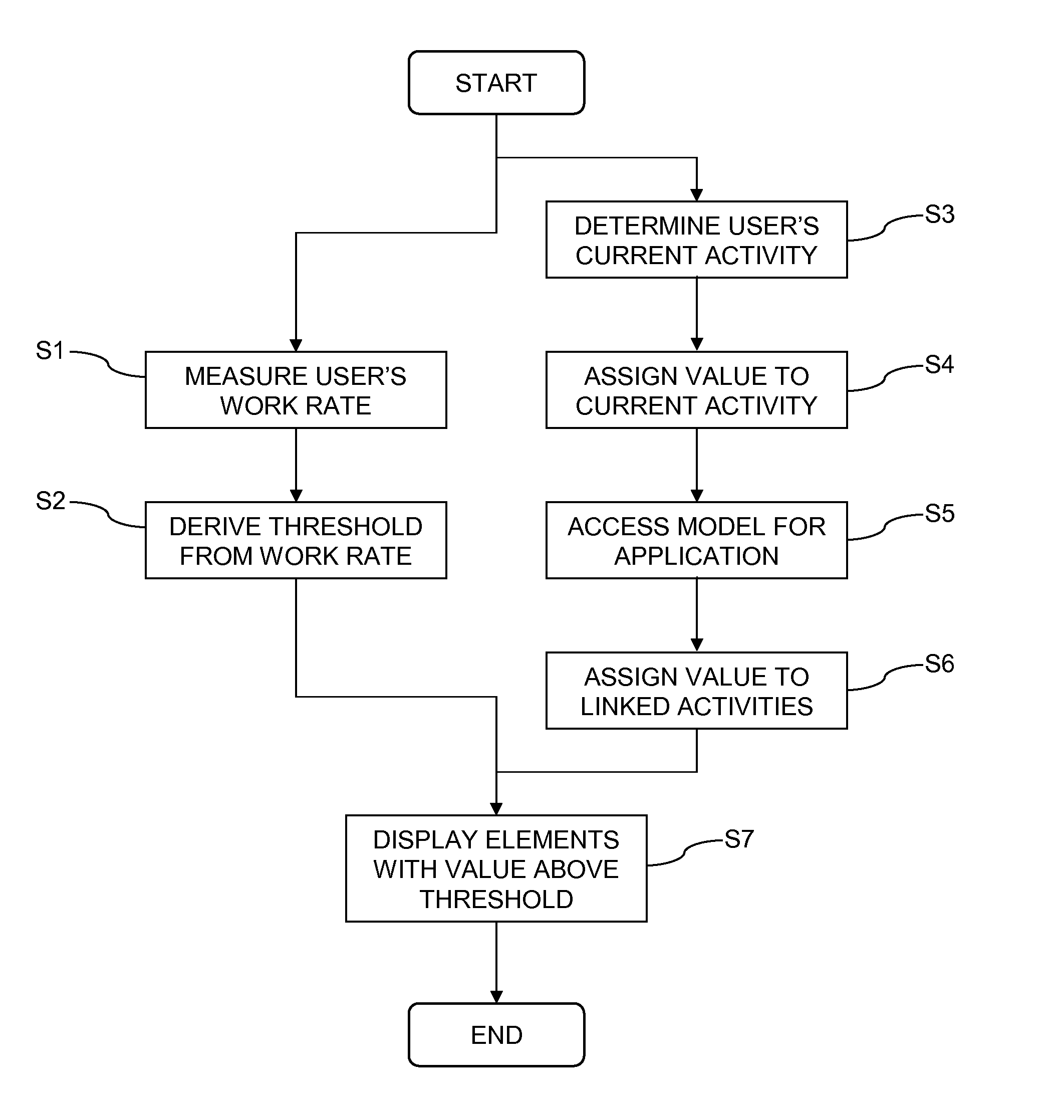
[0026]A method for constructing a graphical user interface and a graphical user interface construction system according to embodiments of the present invention will be described below with reference to the accompanying drawings.

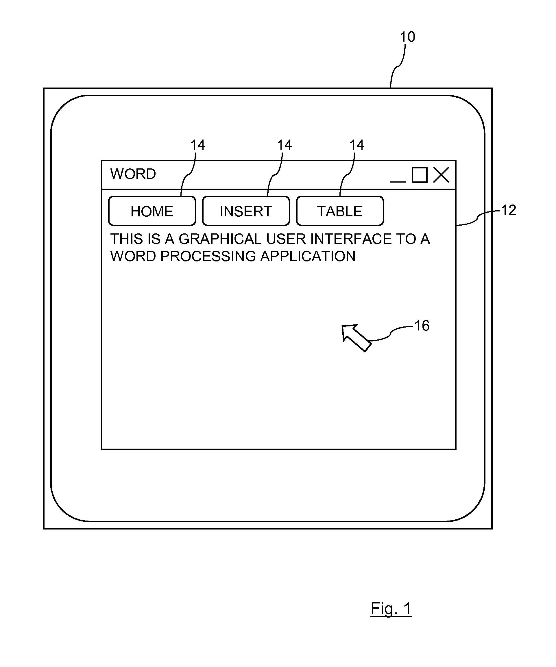
[0027]First, a display device according to an embodiment of the present invention will be described with reference to FIG. 1. As shown in FIG. 1, a display device 10 illustrates a graphical user interface 12 for a word-processing application “WORD”. The display device 10 includes part of a standard desktop computing system, where a user has access to a keyboard and a mouse (not shown) in addition to the display device 10. A processing device is providing the processing power to control the display device 10 under a user's control of the keyboard and mouse. The processing device may be provided locally to the user or may be provided remotely. In this latter case, the processing device is connected to the user's keyboard, mouse and display 10 via a network.

[002...


PUM


Abstract

A system and method for constructing a graphical user interface for an application being accessed by a user are provided. The method includes measuring the user's current work rate, deriving a threshold from the user's current work rate, determining the user's current activity within the application, assigning a value to the user's current activity, accessing a model for the application, the model defining links between activities within the application, assigning values to activities linked within the accessed model to the user's current activity, and displaying a control element in a graphical user interface for each activity with a value above the derived threshold.

Description

BACKGROUND[0001]Embodiments of the present invention relate to constructing a graphical user interface, and in particular, to constructing a graphical user interface for an application being accessed by a user.[0002]User devices such as computers and mobiles phones run applications with which a user can interact via a graphical user interface. When using such an interface it is common for there to be large amounts of superfluous control elements available to the user. A control element is any button, window, icon, or other distinguishable element of the user interface. These extra control elements take up valuable screen space and direct attention away from the task the user is currently performing. Although the user may wish to access all of the control elements at different times, it is very unlikely that they need constant access to all of the different control elements that can be presented to the user.[0003]Existing solutions to these problems include task oriented user interfa...

Claims


Application Information

Patent Timeline
IPC IPC(8): G06F3/048H04M1/72472
CPCH04M1/72586G06F9/4443G06F9/451H04M1/72472
Inventor BROWN, MARTINDRAKARD, DAVID T. G.KNOTT, CHRISTOPHERLUEKE, HENNINGPAPAGEORGIOU, ANTHONY P.SHUNKEVICH, ALENA
Owner IBM CORP
Learn More