Magnetoresistive sensor with reduced parasitic capacitance, and method

Active Publication Date: 2012-06-28
STMICROELECTRONICS SRL
View PDF4 Cites 51 Cited by
  • Summary
  • Abstract
  • Description
  • Claims
  • Application Information

AI Technical Summary

Problems solved by technology

This voltage Voff does not have any relationship with the magnetic field that is to be detected but adds, in an undesirable way, to the signal generated by the transduction of the magnetic field that is to be detected in voltage.
In addition, the process (which is relatively simple) of deposition of the ferromagnetic material, is rendered burdensome by numerous successive process steps to provide various metal levels, considerably increasing the manufacturing costs in terms of number of masks and process cost (machinery, process steps, manufacturing times).
In addition, given the presence of current peaks of a high value, there may arise problems d

Method used


Image

  • Magnetoresistive sensor with reduced parasitic capacitance, and method
  • Magnetoresistive sensor with reduced parasitic capacitance, and method
  • Magnetoresistive sensor with reduced parasitic capacitance, and method

Examples


Embodiment Construction

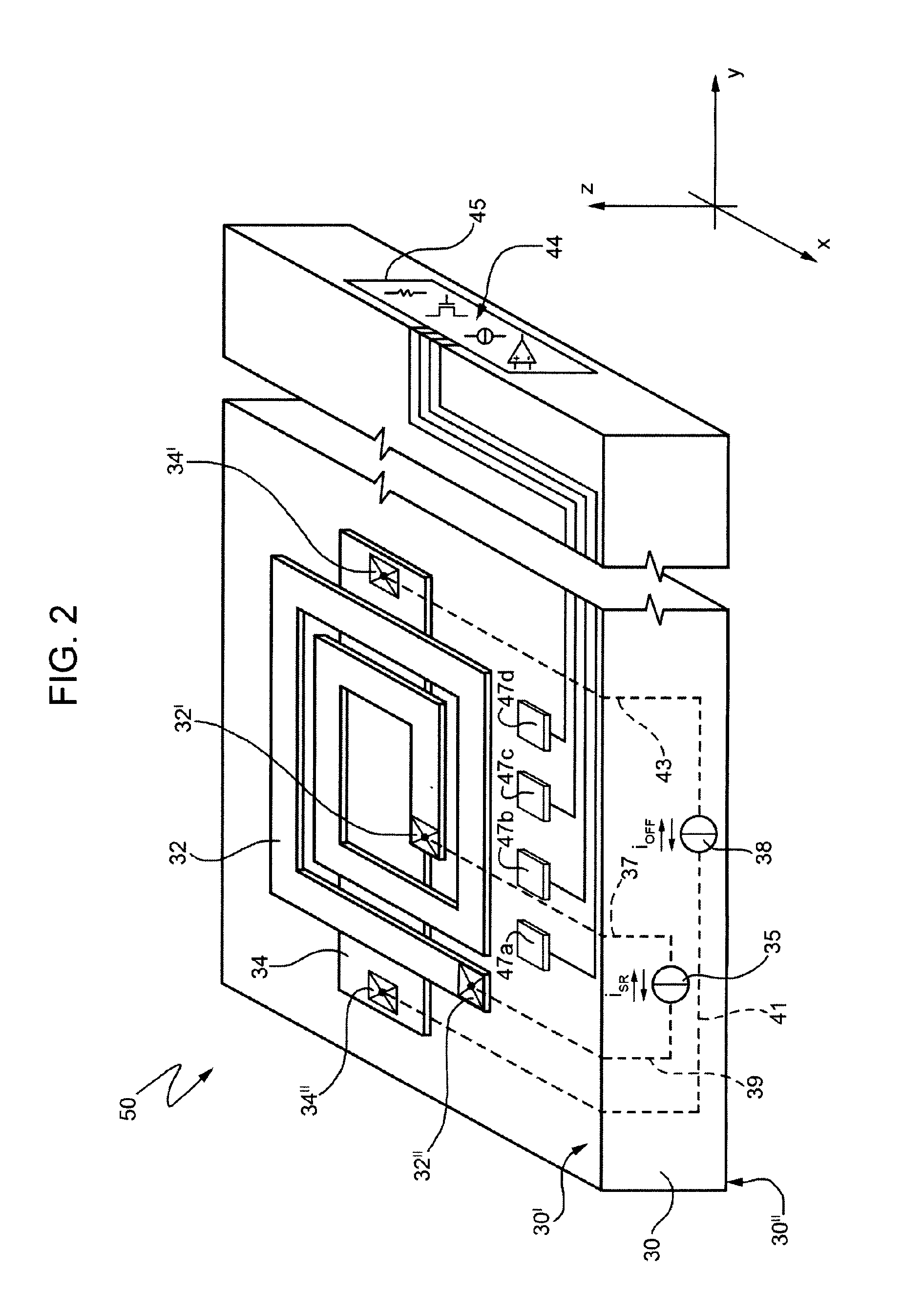
[0036]FIG. 2 is a schematic illustration of an ASIC (application-specific integrated circuit) chip 50, carrying an ASIC 45 for reading and / or electrical biasing of one or more magnetoresistive elements. The ASIC 45 is of a type integrated in a semiconductor substrate 30, and is configured for carrying out reading and / or electrical biasing of magnetoresistive elements in a magnetic-field sensor, of the AMR type. In particular, as described in detail with reference to FIG. 5, said magnetic-field sensor is obtained by assembling together the ASIC chip 50 and a further chip 60, distinct from the ASIC chip 50, carrying the magnetoresistive elements (FIG. 3).

[0037]The ASIC chip 50 comprises, according to an embodiment of the present disclosure, a first element 32 and a second element 34 for generation of magnetic fields. According to one embodiment, the first and second magnetic field generators 32, 34 are formed by a conductive element configured for being traversed by electric current. ...


PUM


Abstract

A magnetic-field sensor adapted to detect an external magnetic field, comprising: a first chip, including a first magnetoresistive structure for detection of the external magnetic field, the first magnetoresistive detection structure including an electrical-contact pad and magnetoresistive means; and a second chip housing an integrated electronic circuit and a magnetic-field generator, the first and second chips being mutually arranged in such a way that the integrated electronic circuit can be electrically coupled to the electrical-contact pad of the magnetoresistive structure and in such a way that the magnetic-field generator can be magnetically coupled to the magnetoresistive structure.

Description

BACKGROUND[0001]1. Technical Field[0002]The present disclosure relates to a magnetic-field sensor, in particular to a sensor that uses anisotropic magnetoresistive (AMR) elements in order to detect a magnetic field that is external to the sensor and acts on the sensor itself.[0003]2. Description of the Related Art[0004]Magnetic-field sensors, in particular AMR sensors based upon anisotropic magnetoresistance, are used in a plurality of applications and systems, for example in compasses, in systems for detection of ferromagnetic materials, in the detection of currents, and in a wide range of other applications, thanks to their capacity for detecting natural magnetic fields (for example, the Earth's magnetic fields) and magnetic fields generated by electrical components (such as electrical or electronic devices and lines traversed by electric current).[0005]The phenomenon of anisotropic magnetoresistivity occurs within particular ferromagnetic materials, which, when subjected to an ex...

Claims


Application Information

Patent Timeline
IPC IPC(8): G01R33/02
CPCB82Y25/00G01R33/093G01R33/0005
Inventor POZZATI, ENRICOBOTTINELLI, FABIOROMANI, CARLO ALBERTO
Owner STMICROELECTRONICS SRL
Why Eureka
Try Eureka