
Pixelated optical filter and method for manufacturing thereof

Inactive Publication Date: 2012-06-28
CSEM CENT SUISSE DELECTRONIQUE & DE MICROTECHNIQUE SA RECH & DEV
View PDF15 Cites 41 Cited by
  • Summary
  • Abstract
  • Description
  • Claims
  • Application Information

AI Technical Summary

Benefits of technology

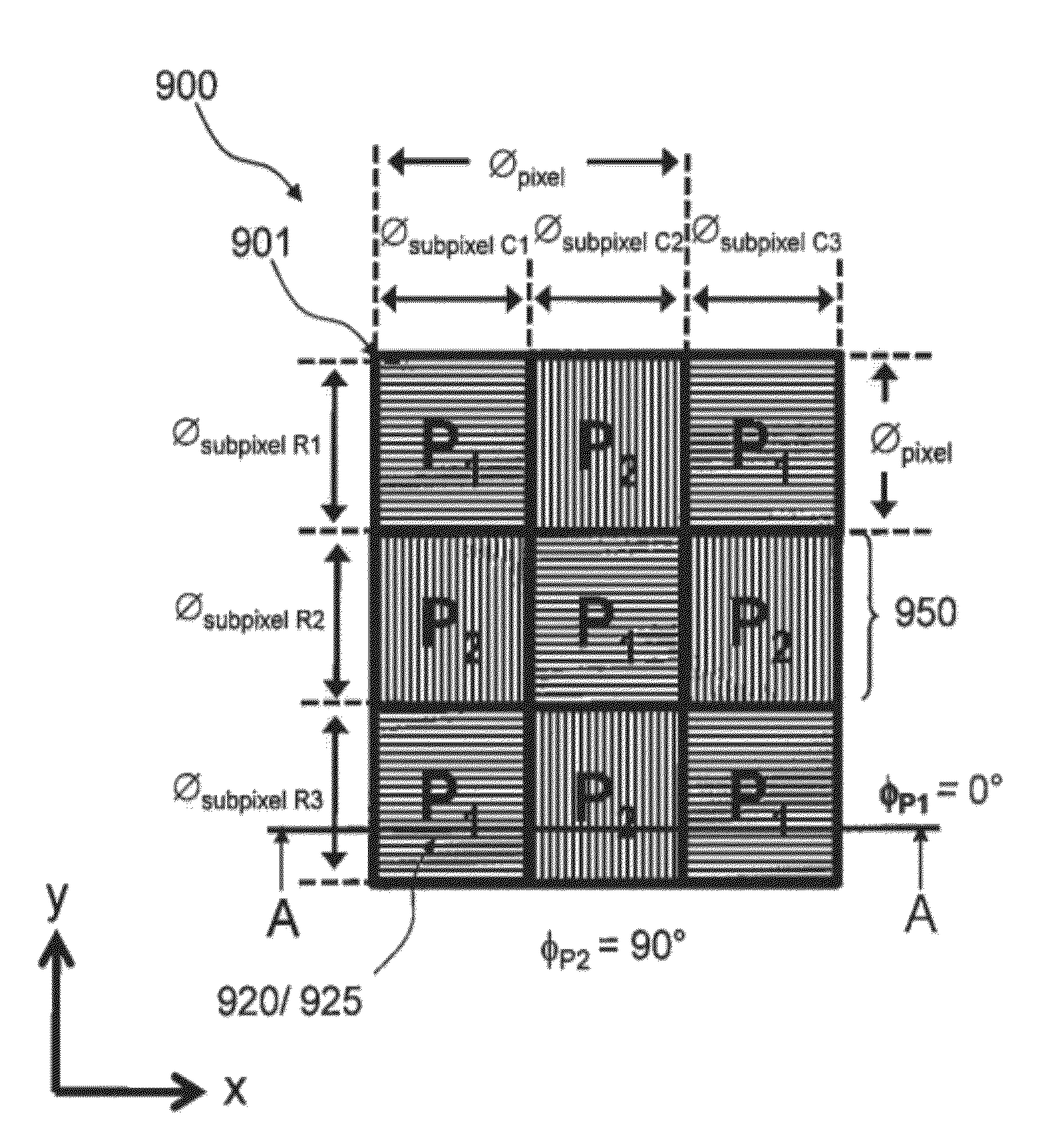
[0094]According to an embodiment of the invention, the plurality of subpixels may be operative to effect a red-green-blue composed colour.
[0

Problems solved by technology

Nevertheless such full colour holograms are only visible on a very narrow viewing angle range due to the high angular sensitivity of the first and higher order diffraction effect.

Method used


Image

  • Pixelated optical filter and method for manufacturing thereof
  • Pixelated optical filter and method for manufacturing thereof
  • Pixelated optical filter and method for manufacturing thereof

Examples


Embodiment Construction

[0071]The term “characteristic colour effect” refers to a spectral curve in transmission and / or reflection purposely effected by a specific design of a pixelated optical filter according to an embodiment of the invention. Examples of a characteristic colour effect or effects may include, for example, characteristic reflection peaks in the visible and / or near infra red spectral region. A reflection peak in the visible spectral range can for example be a measure for a colour observable by the human eye.

[0072]It should be noted that positional terms such as “right”, “left”, “top”, “bottom”, “upper”, “lower”, as used herein do not necessarily indicate that, for example, a “lower” component is below an “upper” component as such directions, components or both may be flipped, rotated, moved in space, placed in a diagonal orientation or position, placed horizontally or vertically, or similarly modified. Accordingly, it will be appreciated that terms such as, for example, “right”, “left”, “t...


PUM


Abstract

The present invention discloses a pixelated optical filter comprising high-index refraction material positioned between low-index-refraction matter. At least some of the high-index refraction material has a grated structure and lateral and vertical dimensions with respect to the low-index-refraction matter such that the high-index refraction material is operative to act as a leaky waveguide for light incident on the pixelated optical filter. The grated structure comprises a plurality of at least one grating pattern that is planarly bounded. Each of the plurality of at least one grating pattern constitutes a subpixel. A plurality of subpixels is operative to diffract incident light to at least one zero-order wavelength spectrum respective of the at least one grating pattern. Additional and alternative embodiments are disclosed and claimed.

Description

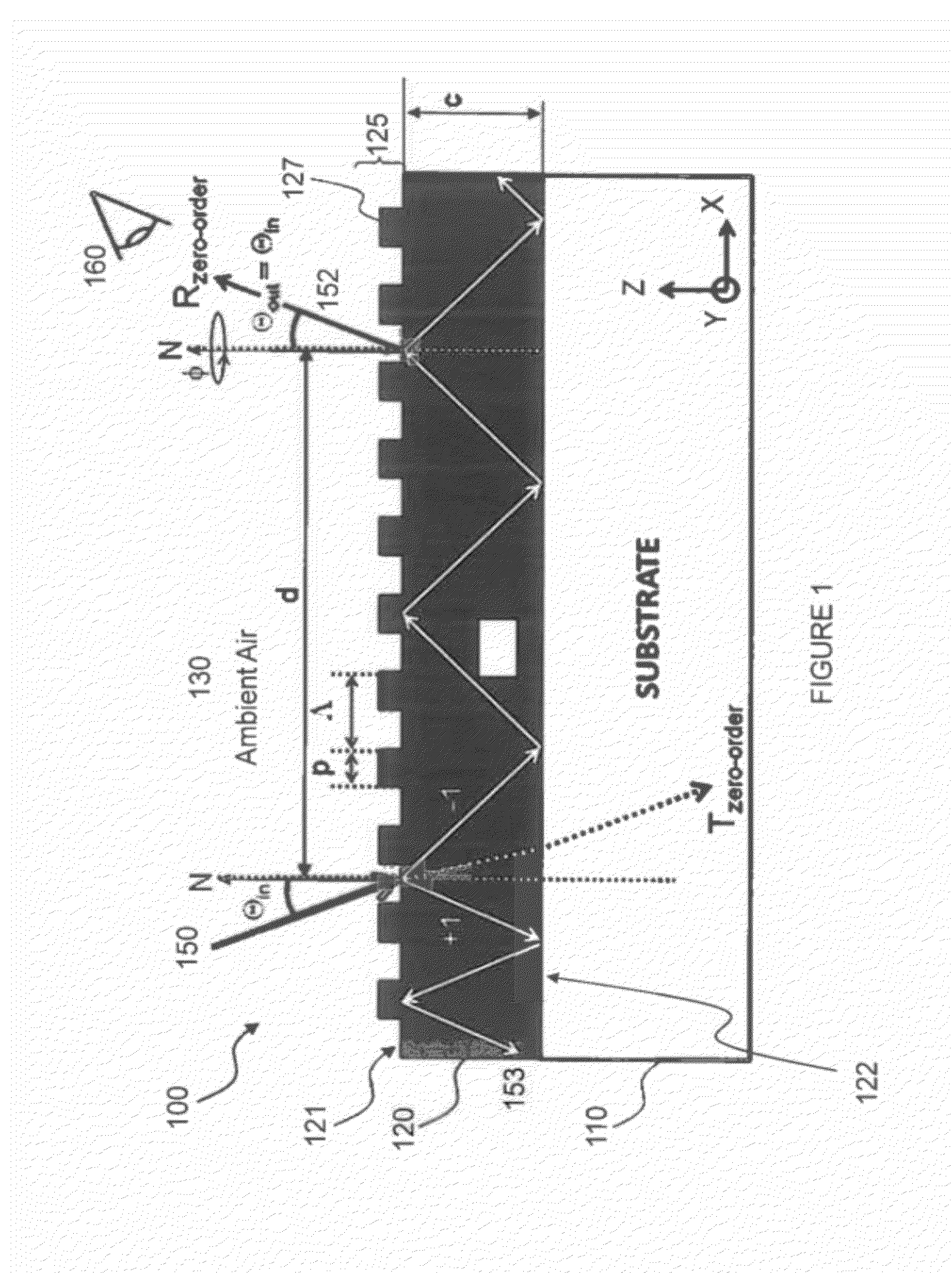
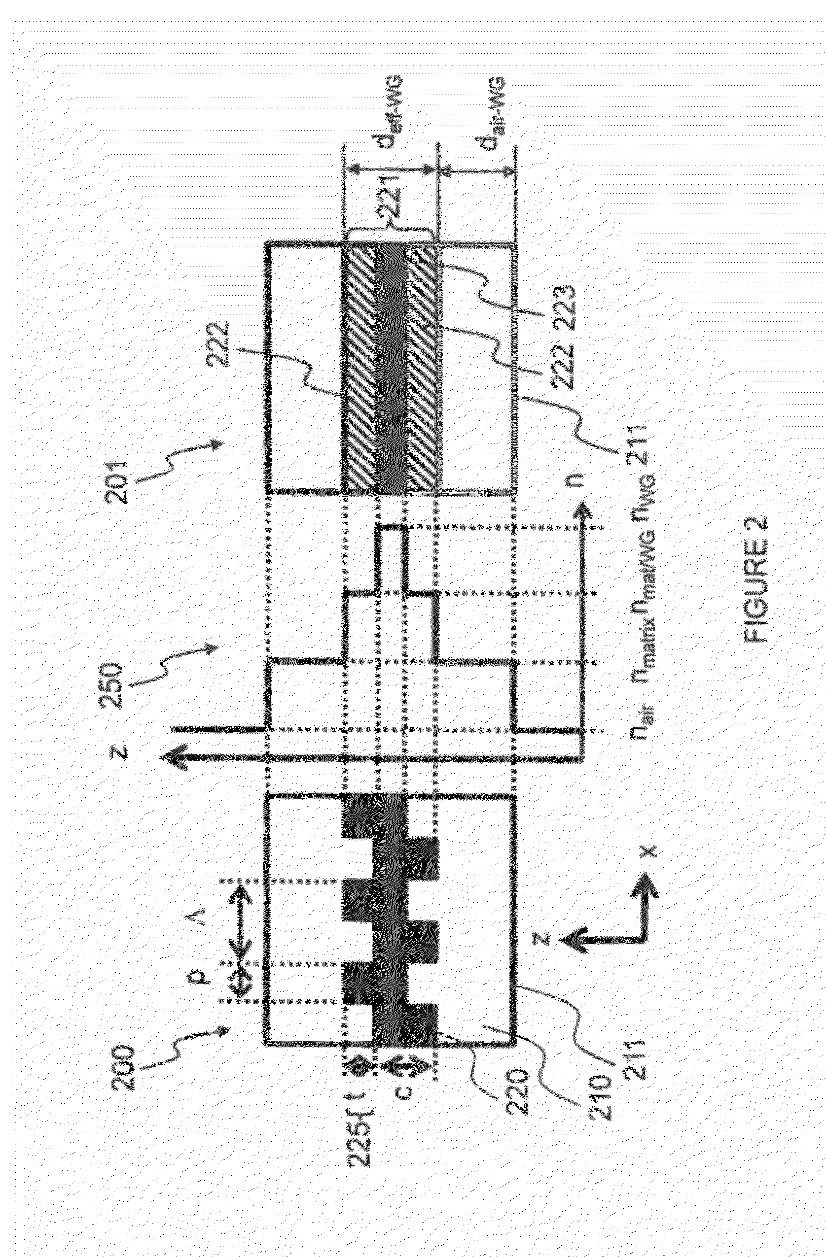
FIELD OF THE INVENTION[0001]The invention pertains to optical filters and more specifically, to Zero-Order Diffractive Filters.BRIEF DESCRIPTION OF THE FIGURES[0002]These and further features and advantages of the invention will become more clearly understood in the light of the ensuing description of embodiments thereof, given by way of example only, with reference to the accompanying figures, wherein:[0003]FIG. 1 is a schematic side-view illustration of a first zero-order diffractive filter as known in the art, and of the corresponding behaviour of light incident thereon;[0004]FIG. 2 is a schematic side view illustration of a second ZOF as known in the art, of the corresponding index of refraction profile in Z-direction, and of the corresponding virtual equivalent (VE) multilayer design assuming homogeneous layers in the X-Y-plane with the respective averaged indices of refraction;[0005]FIG. 3 is a schematic side view illustration of a third ZOF as known in the art, of the corresp...

Claims


Application Information

Patent Timeline
IPC IPC(8): G02B5/18B29D11/00
CPCB42D2035/14B42D2035/24G02B5/1809B42D25/328G02B5/1885G02B5/201B42D25/29G02B5/1847G03H1/0011B42D25/425
Inventor WALTER, HARALDPETITON, VALERYLUU-DINH, ANGELIQUENOIZET, ALEXANDRE
Owner CSEM CENT SUISSE DELECTRONIQUE & DE MICROTECHNIQUE SA RECH & DEV
Learn More