Solar powered lighting arrangement

a solar energy and lighting technology, applied in fixed installations, lighting and heating equipment with built-in power, etc., can solve the problems that normal lighting solutions may not be feasible in many of these rural areas

Inactive Publication Date: 2012-06-28
SIGNIFY HLDG BV +1
View PDF3 Cites 3 Cited by
  • Summary
  • Abstract
  • Description
  • Claims
  • Application Information

AI Technical Summary

Benefits of technology

[0017]In order to be able to provide e.g. a softer light from the light source, the solar powered lighting arrangement may further comprise a diffuser layer for diffusing light emitted from the light source. By applying such a layer for instance in the vicinity of the light source, light emitted from the light source may be scattered or spread in a manner appropriate for the implement...

Problems solved by technology

Normal lighting solutions may however not be feasible in many of these rural...

Method used


Image

  • Solar powered lighting arrangement
  • Solar powered lighting arrangement
  • Solar powered lighting arrangement

Examples


first embodiment

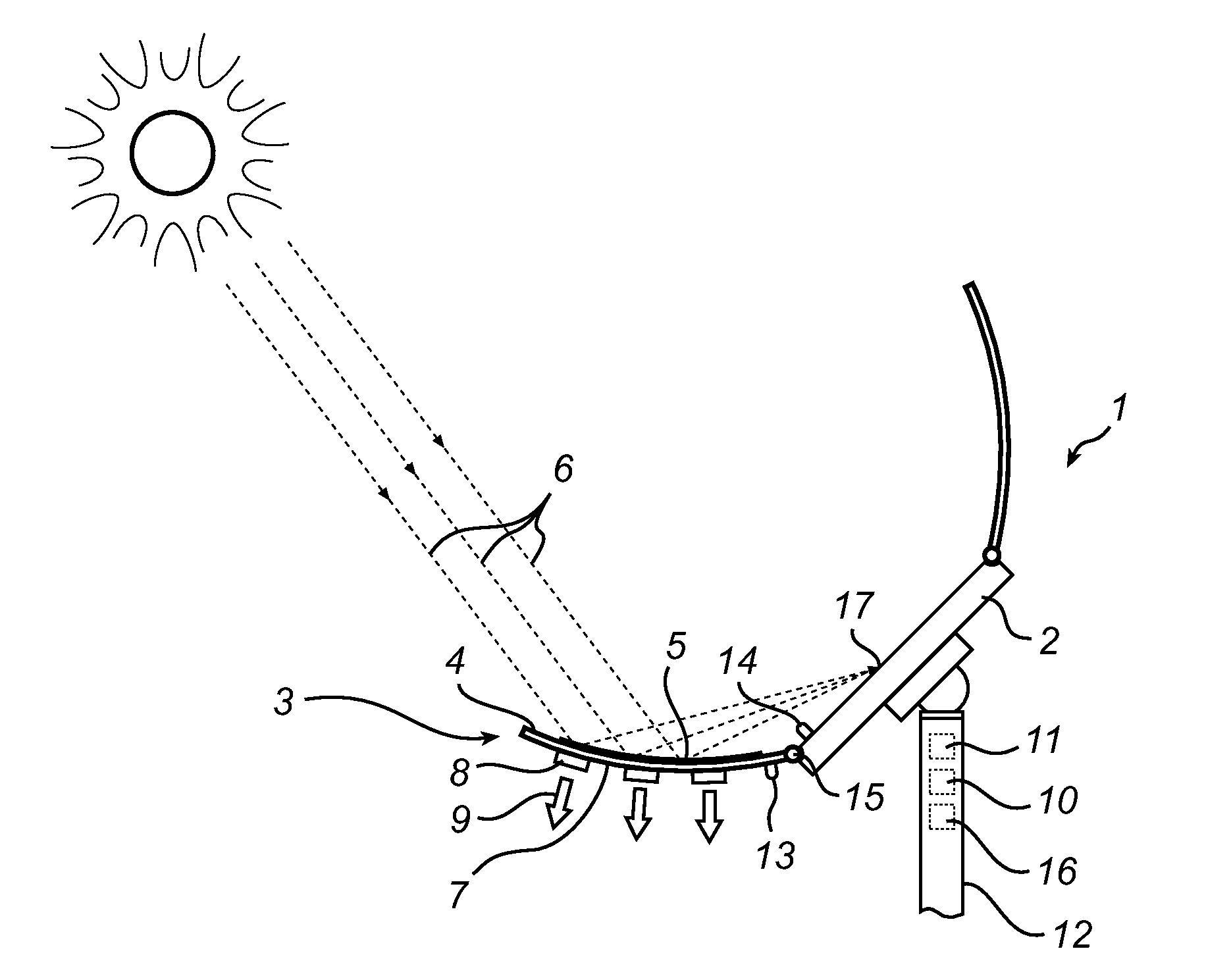
[0024]FIG. 1 illustrates an exemplifying solar powered lighting arrangement 1 in accordance with the present invention. For simplicity, the solar powered lighting arrangement 1 of FIG. 1 comprises a single solar cell 2. Note however, that more than one solar cell may be present with the solar powered lighting arrangement 1 such as an interconnected assembly of a plurality of solar cells. The illustrated single solar cell 2 may hence likewise be one or several solar panels which further may be provided with a covering hood for protection from the surrounding environment. It is to be understood that the solar cell 2 may be represented by any applicable solar cell or panel known in the art, and that the solar cell 2 may be adapted to generate electrical power in a known manner. In order to envisage the ability of the solar powered arrangement 1 to derive electrical power from the solar cell 2, a means for deriving electrical power 10 is illustrated. The means for deriving electrical po...

second embodiment

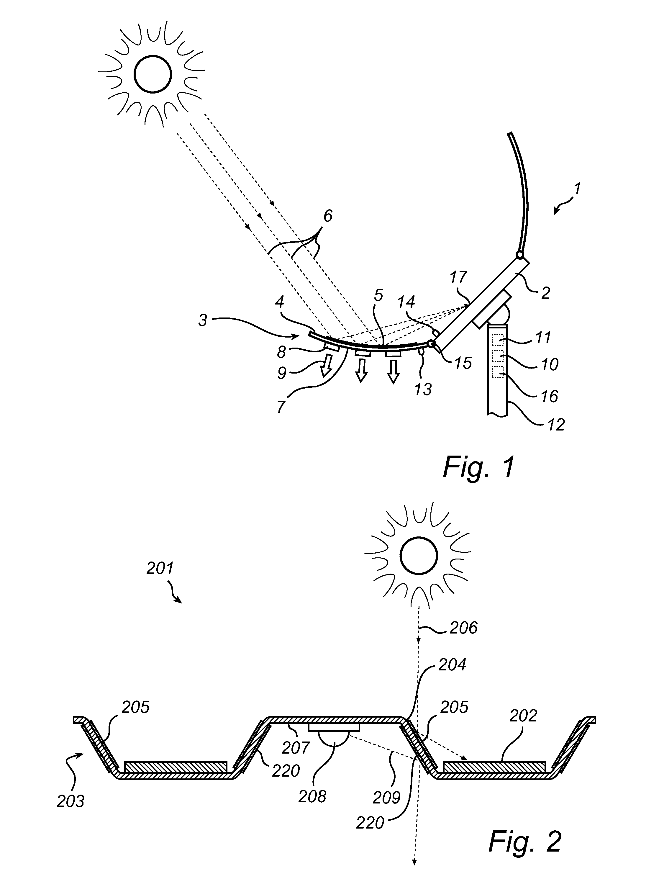
[0035]FIG. 2 presents an exemplifying solar powered lighting arrangement 201 in accordance with the present invention. The illustrated solar powered lighting arrangement 201 resembles that 1 described in conjunction with FIG. 1, why only distinctive differences are discussed in the following.

[0036]The solar powered lighting arrangement 201 of FIG. 2 is in contrast to that of FIG. 1 shaped to be convenient for instance for indoor lighting. The structural member 203 is here a large structure making part of a corrugated roof of a simple shed, with the first side 204 of the structural member 203 facing the sun and the second side 207 facing the inside of the shed. Note that the structure 203 neither necessarily is corrugated, nor necessarily is part of a roof; other implementations may likewise be applicable.

[0037]The solar powered lighting arrangement 201 here comprises a plurality of solar cells or panels 202 arranged on top of the structural member 203, i.e. on the first side 204. Th...

third embodiment

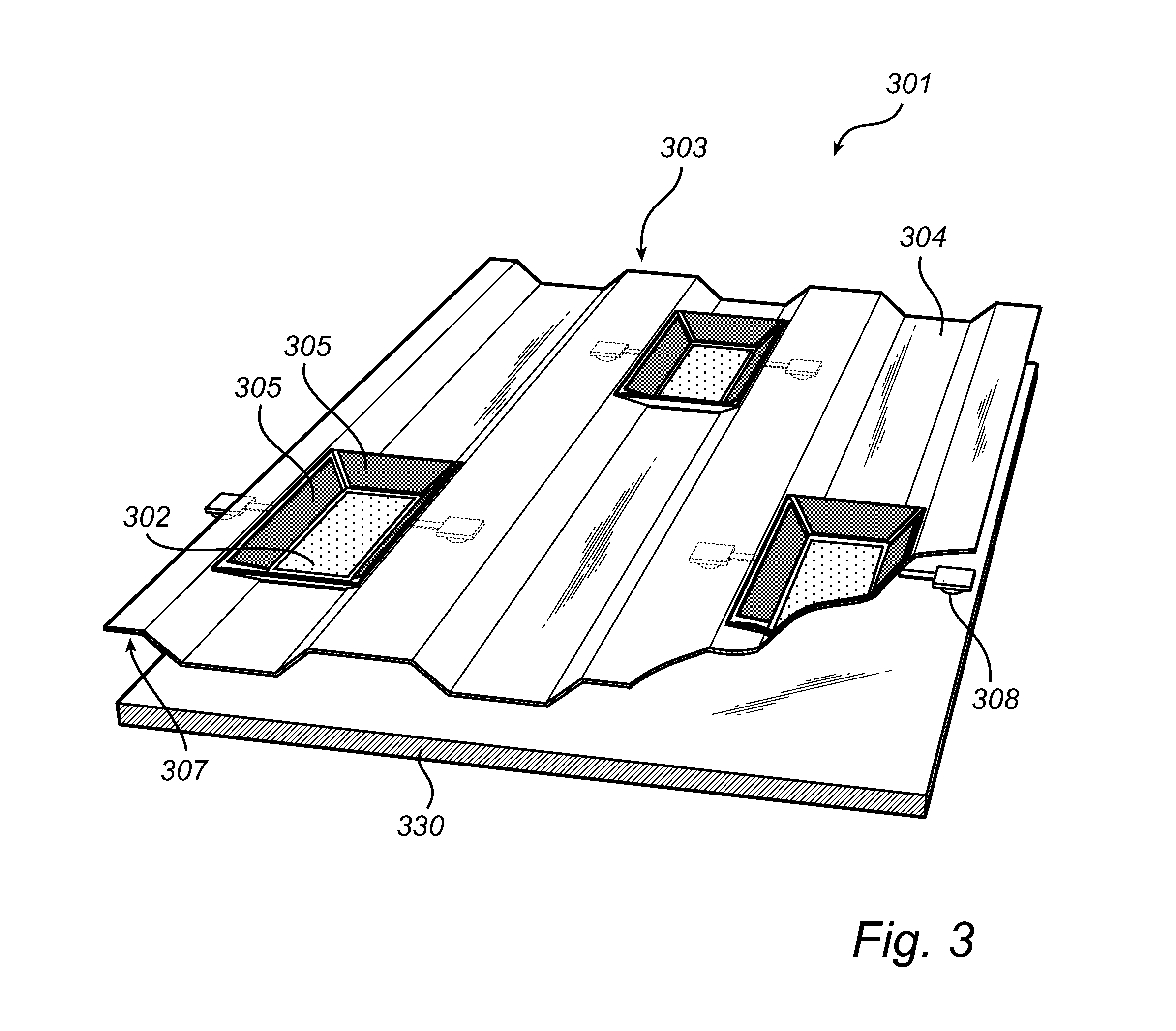
[0040]FIG. 3 illustrates in a three-dimensional view an exemplifying solar powered lighting arrangement 301 in accordance with the present invention. The illustrated solar powered lighting arrangement 301 resembles those described in conjunction with FIGS. 1 and 2, why only distinctive differences are discussed in the following.

[0041]The structural member 303 of FIG. 3 is here a large structure making part of a corrugated metal roof, and may hence similar to the second embodiment of FIG. 2 be convenient for instance for indoor lighting. The solar powered lighting arrangement 301 of FIG. 3 comprises a plurality of solar cells or panels 302 arranged across the first side 304 of the structural member 303 and a plurality of light sources 308 arranged across the second side. Each solar cell 302 is here provided with four first reflective surfaces 305 for directing sunlight towards the corresponding solar cell 302, and two light sources 308. Note that the positioning as well as the number...


PUM


Abstract

A solar powered lighting arrangement (1), comprising a solar cell (2); a light source (8) adapted to be at least partly powered by electrical power derived from the solar cell (2); and a structural member (3) having a first side (4) provided with a first reflective surface (5) arranged to direct sunlight (6) towards the solar cell (2) and a second side (7) onto which the light source (8) is thermally coupled for dissipating heat generated by the light source (8) when emitting light (9). With the provision of a solar powered lighting arrangement in accordance with the present invention, the structural member may consequently function not only as a reflecting surface directing sunlight towards the solar cell, but additionally as a heat sink for the light source.

Description

FIELD OF THE INVENTION[0001]The present invention relates to a solar powered lighting arrangement comprising a solar cell and a light source adapted to be at least partly powered by electrical power derived from the solar cell.DESCRIPTION OF THE RELATED ART[0002]Bringing artificial light to rural areas may be an approach for development of communities as well as countries. Normal lighting solutions may however not be feasible in many of these rural areas as they often are off-grid, i.e. not covered by power transmission networks. In such situations, one known manner to bring light may be to install solar powered lighting utilizing photovoltaic cells (solar cells) for the purpose of electrical power production. Electrical power may be stored in rechargeable batteries for subsequent use; for instance to power one or several luminaries comprising light sources, which may bring light to the rural area during dark hours.[0003]In order to reduce expenses related to electrical power produc...

Claims


Application Information

Patent Timeline
IPC IPC(8): F21L4/02F21L4/00F21V29/505
CPCF21S8/08F21S9/035F21V29/004F21Y2101/02H01L31/0547F21S9/037F21V29/505F21V29/70Y02E10/52F21Y2115/10F21Y2115/15Y10S362/80
Inventor VISSER, PETER
Owner SIGNIFY HLDG BV
Why Eureka
Try Eureka