Image coding method, image decoding method, image coding apparatus, image decoding apparatus, and image coding and decoding apparatus
- Summary
- Abstract
- Description
- Claims
- Application Information
AI Technical Summary
Benefits of technology
Problems solved by technology
Method used
Image

Examples
embodiment 1
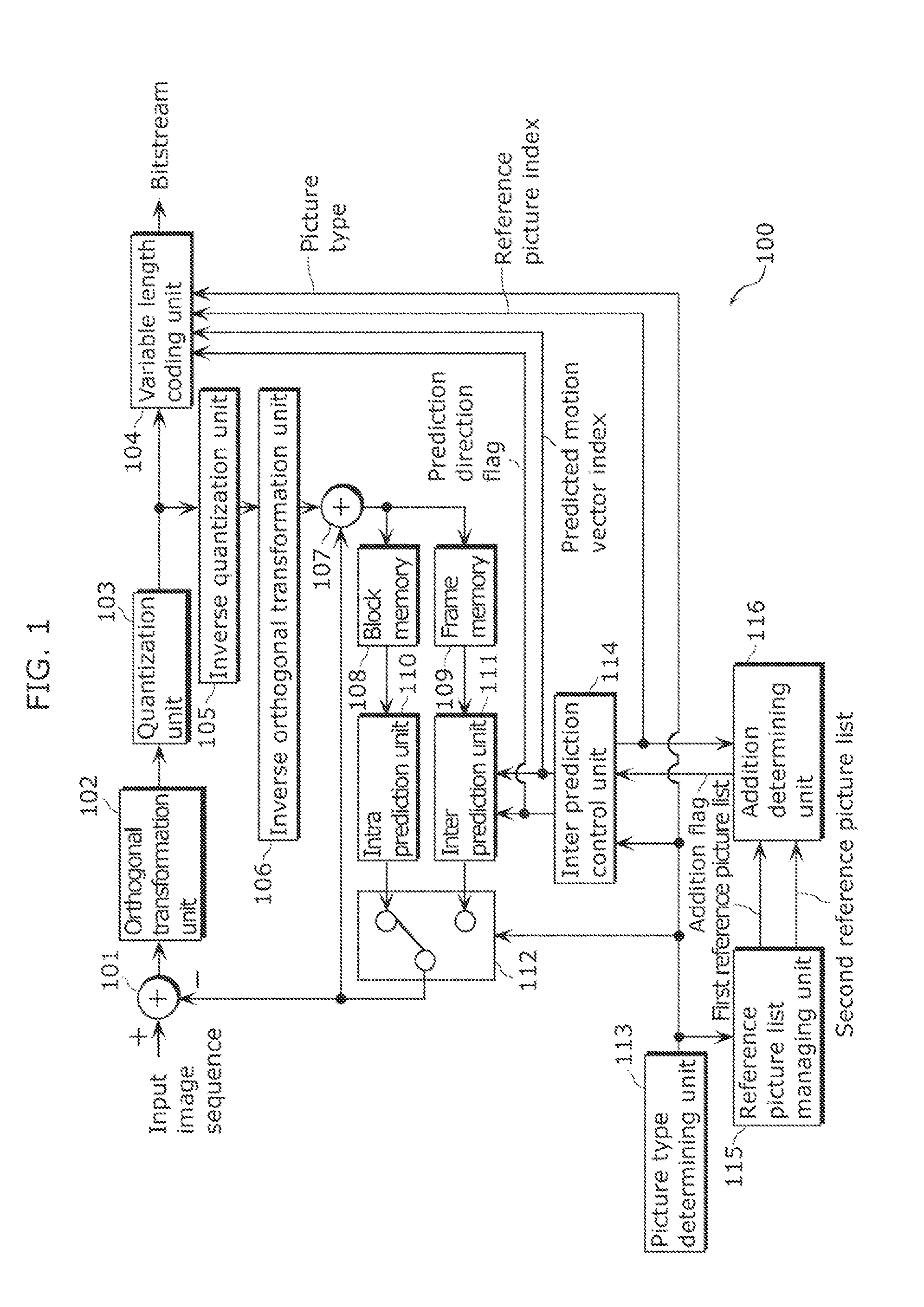
[0116]FIG. 1 is a block diagram illustrating a configuration of an image coding apparatus according to Embodiment 1.
[0117]An image coding apparatus 100 in FIG. 1 includes an orthogonal transformation unit 102, a quantization unit 103, an inverse quantization unit 105, an inverse orthogonal transformation unit 106, a block memory 108, a frame memory 109, an intra prediction unit 110, an inter prediction unit 111, an inter prediction control unit 114, a picture type determining unit 113, a reference picture list managing unit 115, an addition determining unit 116, a variable length coding unit 104, a subtracting unit 101, an addition unit 107, and a switch unit 112.
[0118]The orthogonal transformation unit 102 performs transformation on predicted error data between predicted image data generated by a unit to be described later and an input image sequence from an image domain to a frequency domain. The quantization unit 103 quantizes the predicted error data transformed into the frequen...
embodiment 2
[0185]FIG. 9 is a block diagram illustrating a configuration of an image decoding apparatus according to Embodiment 2.
[0186]As illustrated in FIG. 9, an image decoding apparatus 200 includes a variable length decoding unit 204, an inverse quantization unit 205, an inverse orthogonal transformation unit 206, an addition unit 207, a block memory 208, a frame memory 209, an intra prediction unit 210, an inter prediction unit 211, a switch unit 212, an inter prediction control unit 214, a reference picture list managing unit 215, and an addition determining unit 216.
[0187]The variable length decoding unit 204 variable-length-decodes an input bitstream. Then, the variable length decoding unit 204 generates a picture type, a reference picture index, inter prediction direction information, a predicted motion vector index, and quantized coefficients. The inverse quantization unit 205 inversely quantizes the quantized coefficients. The inverse orthogonal transformation unit 206 performs tran...
embodiment 3
[0209]Embodiment 3 supplementarily describes an image coding apparatus including the characteristic constituent elements of the image coding apparatus 100 according to Embodiment 1.
[0210]FIG. 11A illustrates a configuration of the image coding apparatus according to Embodiment 3. An image coding apparatus 300 in FIG. 11A includes an addition unit 301, a selecting unit 302, and a coding unit 303. The addition unit 301 mainly corresponds to the addition determining unit 116 according to Embodiment 1. The selecting unit 302 mainly corresponds to the inter prediction control unit 114 according to Embodiment 1. The coding unit 303 mainly corresponds to the variable length coding unit 104 according to Embodiment 1.
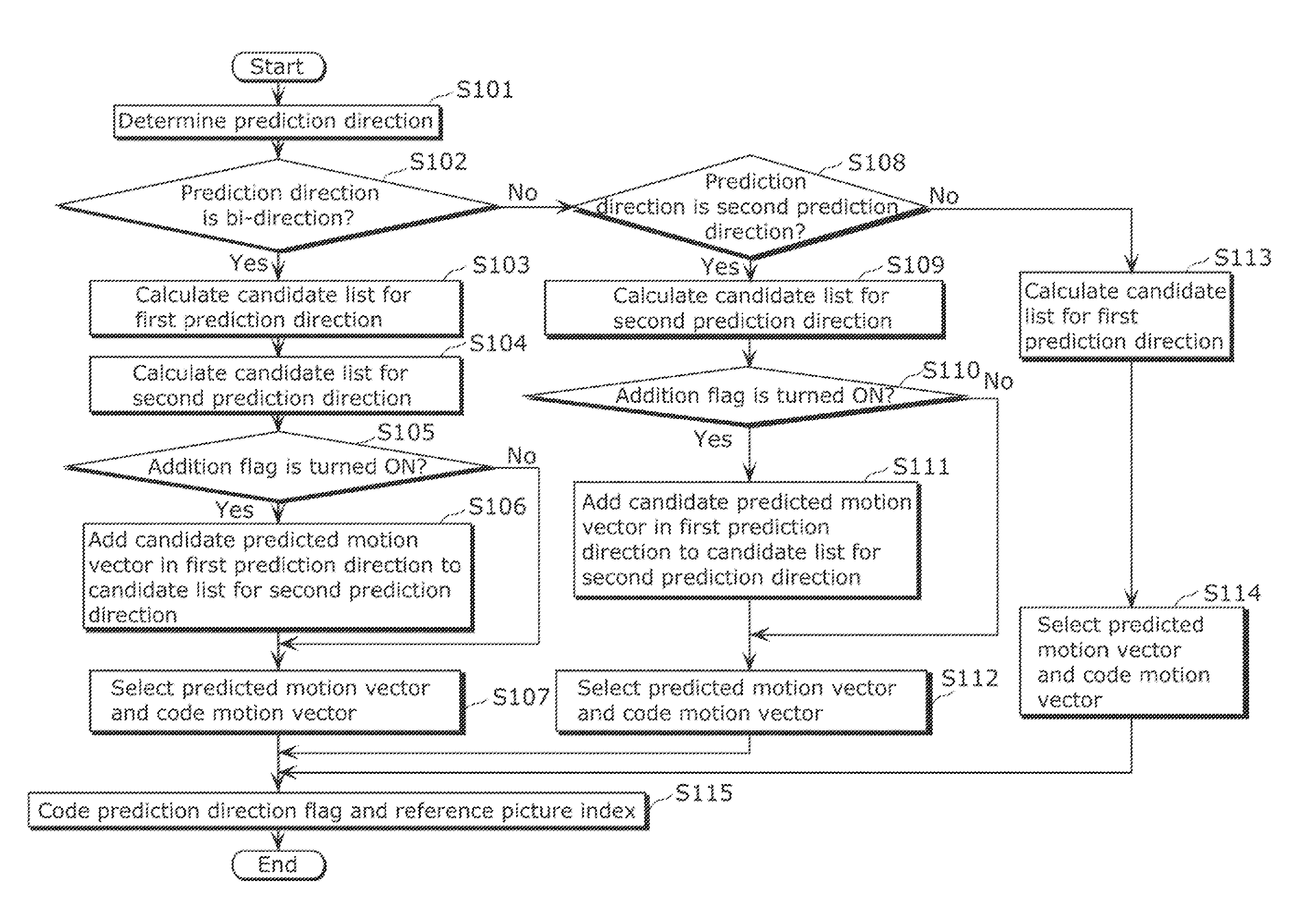
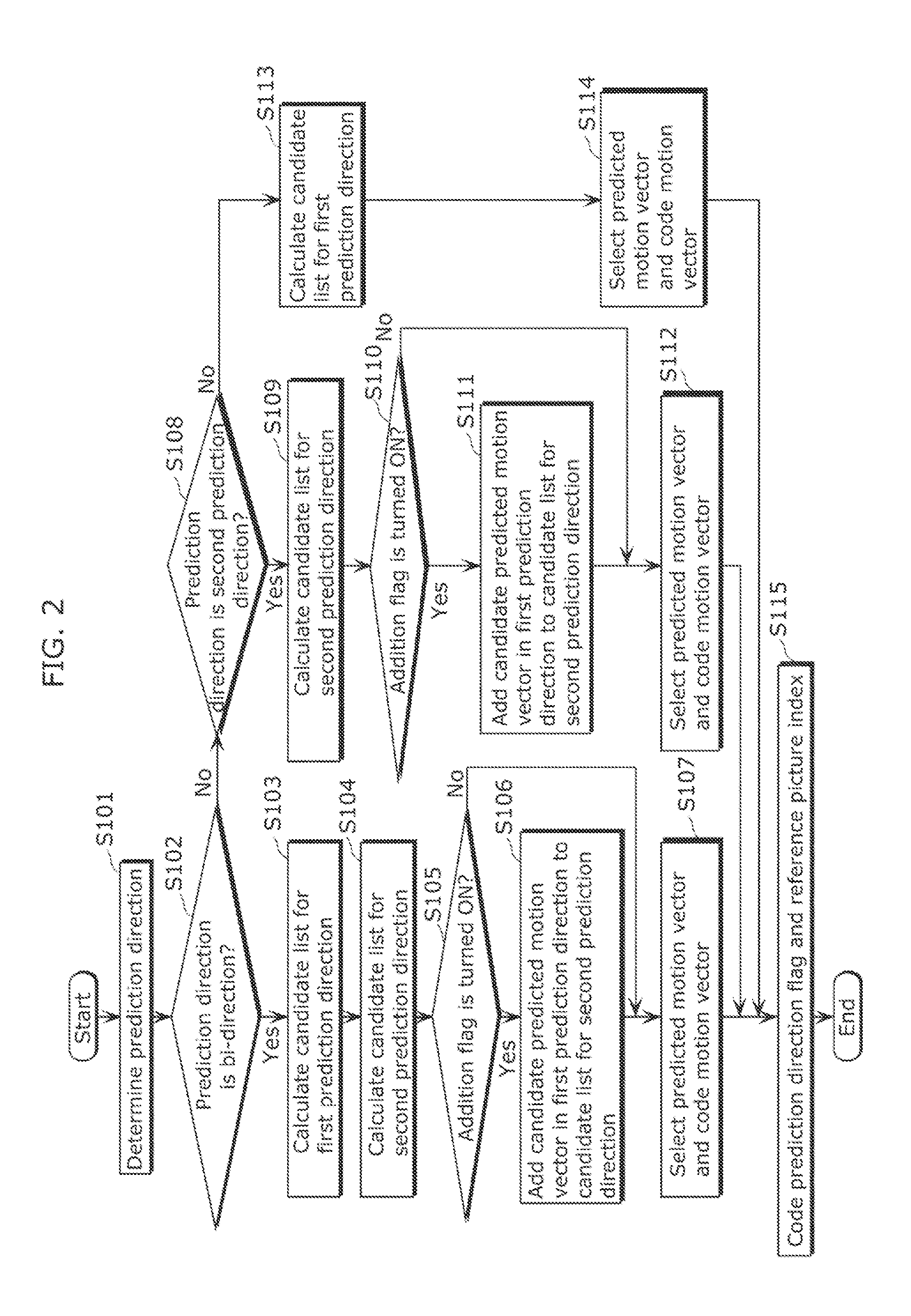
[0211]Then, the image coding apparatus 300 codes the current picture per block. Here, the image coding apparatus 300 performs prediction using one or both of the first and second reference picture lists. In other words, the image coding apparatus 300 performs prediction using on...
PUM
 Abstract
Description
Claims
Application Information
 - R&D
- Intellectual Property
- Life Sciences
- Materials
- Tech Scout
- Unparalleled Data Quality
- Higher Quality Content
- 60% Fewer Hallucinations
Browse by: Latest US Patents, China's latest patents, Technical Efficacy Thesaurus, Application Domain, Technology Topic, Popular Technical Reports.
© 2025 PatSnap. All rights reserved.Legal|Privacy policy|Modern Slavery Act Transparency Statement|Sitemap|About US| Contact US: help@patsnap.com