
Method of controlling audio recording and electronic device

a technology of electronic devices and audio recording, applied in the direction of transducer details, electrical transducers, electrical apparatus, etc., can solve the problems of difficult to address background noise, impose constraints on which technologies, and may be difficult to solve, etc., and achieve high accuracy

Active Publication Date: 2012-06-28
SONY CORP
View PDF4 Cites 92 Cited by
  • Summary
  • Abstract
  • Description
  • Claims
  • Application Information

AI Technical Summary

Benefits of technology

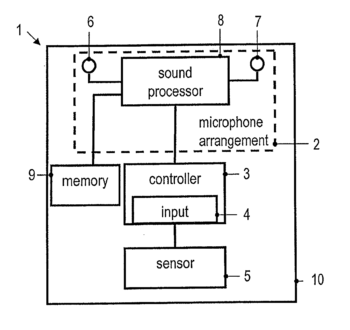
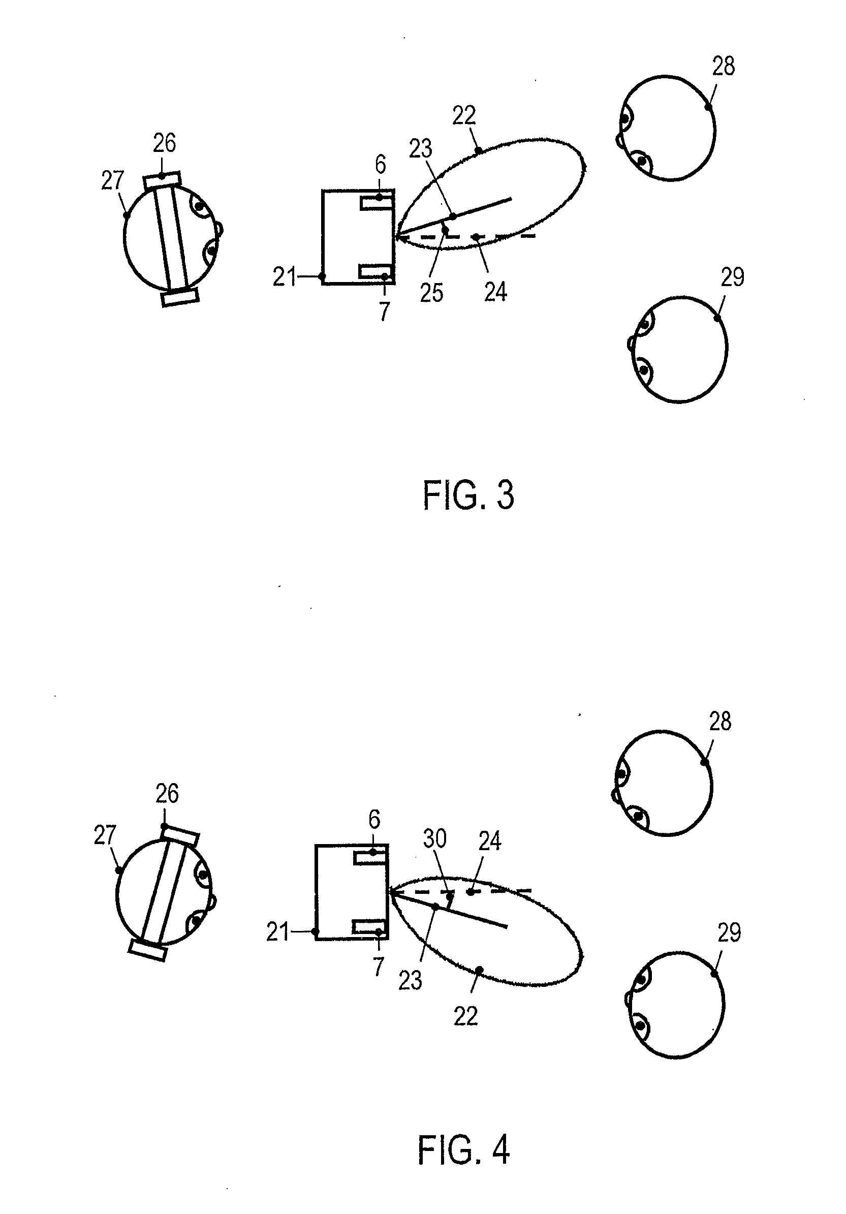
[0008]In the method, the angular orientation of the directivity pattern is controlled relative to the electronic device. Thereby, sound coming from a sound source located at different orientations relative to the electronic device can be recorded with improved signal to noise (S / N) ratios, without requiring the orientation of the electronic device to be re-adjusted. With the target direction being determined responsive to sensor data captured using a sensor different from the microphone arrangement, good S / N can be attained even if the sound source for which the audio recording is to be performed has a sound level smaller than that of a background sound source. With the target direction being determined automatically in response to the sensor data, and with the microphone arrangement being controlled automatically, the method may be performed without requiring a dedicated user confirmation. This makes the audio recording more convenient to the user.
[0014]The sound capturing lobe of the directivity pattern may be disposed on a first side relative to a plane defined by the microphone arrangement, and the sensor data used as a control input may represent a portion of the area surrounding the electronic device which is disposed on a second side opposite the first side. In other words, the sensor data defining a control input for the audio recording may be captured on one side relative to the plane defined by the microphone arrangement, while the microphone arrangement has highest sensitivity on the other side of the plane defined by the microphone arrangement. This allows a user to perform audio recording by holding the electronic device so that it is interposed between the sound source(s) and the user, while the captured sensor data may be representative of the user positioned behind the electronic device (as seen from the sound source(s)).
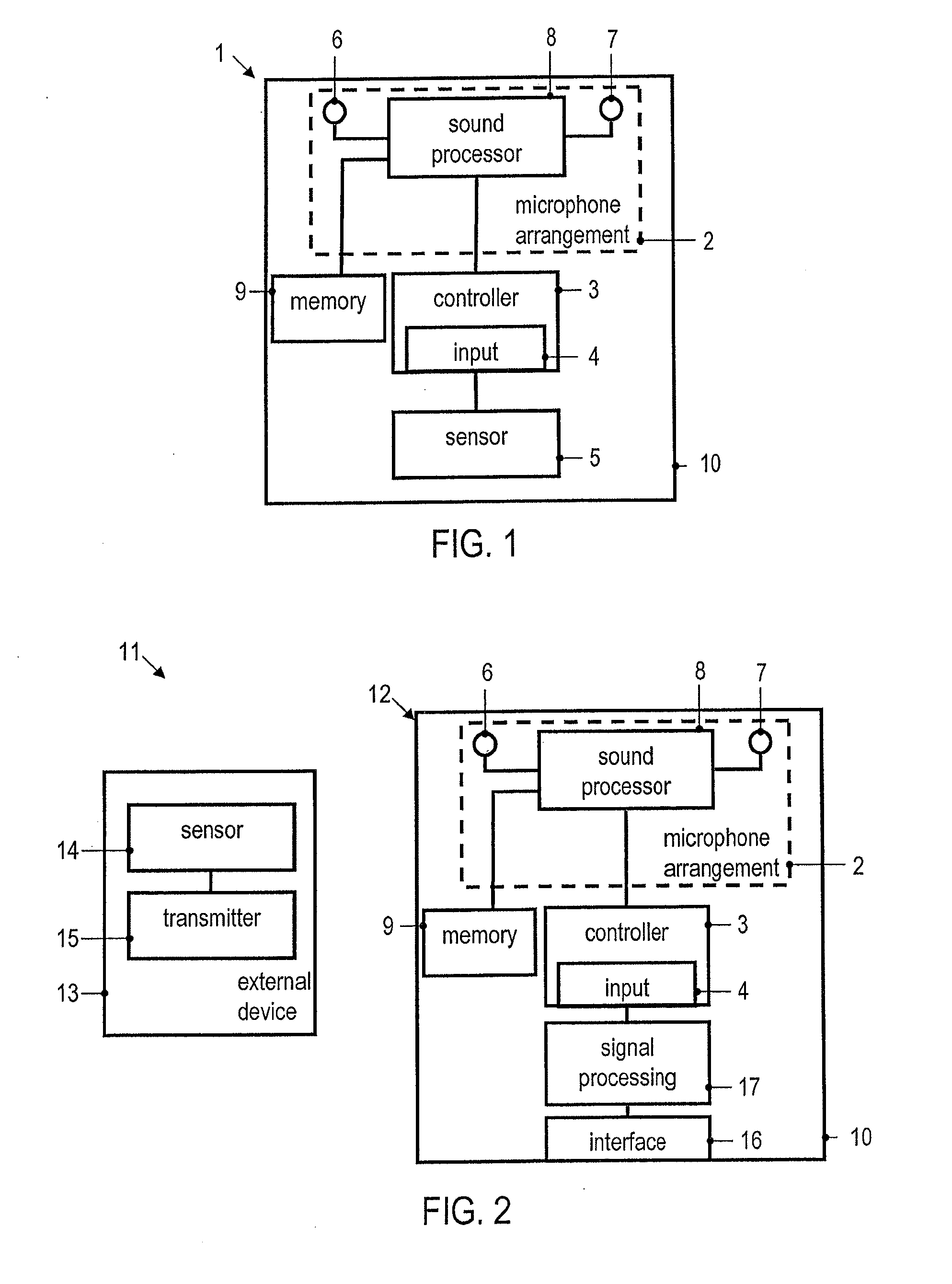
[0016]The sensor may monitor a portion of a user's body which is spaced from the electronic device to capture the sensor data. This allows the angular characteristics of the microphone arrangement to be controlled by the user's body, without requiring the user to perform specific touch-based input functions on the electronic device. Various configurations of such sensors may be implemented. The sensor may be a sensor integrated into a headset worn by the user. The sensor may also be a video sensor integrated in the electronic device.
[0019]The sensor may comprise sensor components integrated into a headset worn by the user. This may allow sensor data indicative of a facial direction and / or eye gaze direction to be determined with high accuracy. Further, such an implementation of the sensor allows the angular characteristics of the microphone arrangement to be controlled in a manner which is not limited by a field of view of an image sensor.

Problems solved by technology

Background noise may be a problem in many application scenarios.
Such problems may be particularly difficult to address in cases where the electronic device is not a dedicated device for audio recording purposes, but has additional functionalities.
In such cases, limited construction space as well as cost issues may impose constraints on which technologies may be implemented in the electronic device to address background noise problems.
This may be inconvenient in some situations, and even close to impossible in other situations, such as when there are several sound sources in one image frame.
Relying on the output signals of a microphone array for controlling the audio recording may be undesirable for various reasons.
For illustration, if the dominant sound source is different from the one the user is actually interested in, deriving a direction estimate based on the sound signals received at plural microphones may not allow the quality of sound recording to be enhanced for the desired sound source.

Method used


Image

  • Method of controlling audio recording and electronic device
  • Method of controlling audio recording and electronic device
  • Method of controlling audio recording and electronic device

Examples


Embodiment Construction

[0048]In the following, embodiments of the invention will be described in detail with reference to the accompanying drawings. It is to be understood that the following description of embodiments is not to be taken in a limiting sense. The scope of the invention is not intended to be limited by the embodiments described hereinafter or by the drawings, which are taken to be illustrative only.

[0049]The drawings are to be regarded as being schematic representations, and elements illustrated in the drawings are not necessarily shown to scale. Rather, the various elements are represented such that their function and general purpose become apparent to a person skilled in the art. Any connection or coupling between functional blocks, devices, components or other physical or functional units shown in the drawings or described herein may also be implemented by an indirect connection or coupling. Functional blocks may be implemented in hardware, firmware, software or a combination thereof.

[005...


PUM


Abstract

A method of controlling audio recording using an electronic device and an electronic device are described. The electronic device comprises a microphone arrangement having a directivity pattern. A target direction relative to the electronic device is automatically determined in response to sensor data representing at least a portion of an area surrounding the electronic device. The microphone arrangement is automatically controlled in response to the determined target direction to adjust an angular orientation of the directivity pattern relative to the electronic device.

Description

[0001]The invention relates to a method of controlling audio recording using an electronic device and to an electronic device. The invention relates in particular to such a method and device for use with a directional microphone which has a directivity pattern.BACKGROUND OF THE INVENTION[0002]A wide variety of electronic devices nowadays is provided with equipment for recording audio data. Examples for such electronic devices include portable electronic devices which are intended to simultaneously record audio and video data. Examples include modern portable communication devices or personal digital assistants. There is an increasing desire to configure such devices so as to allow a user to record audio data, possibly in combination with video data, originating from an object located at a distance from the electronic device.[0003]Background noise may be a problem in many application scenarios. Such problems may be particularly difficult to address in cases where the electronic devic...

Claims


Application Information

Patent Timeline
IPC IPC(8): H04R3/00
CPCH04R1/406H04R3/005H04S2400/15H04S7/304H04R2499/11
Inventor SIOTIS, GEORGABRAHAMSSON, MAGNUSNYSTROM, MARTIN
Owner SONY CORP
Learn More