Reconfigurable optical add-drop multiplexer
a multiplexer and optical add-drop technology, applied in optical multiplex, wavelength-division multiplex systems, instruments, etc., can solve problems such as the challenge of monitoring these channels, and achieve the effect of high degree of flexibility
- Summary
- Abstract
- Description
- Claims
- Application Information
AI Technical Summary
Benefits of technology
Problems solved by technology
Method used
Image
Examples
first embodiment
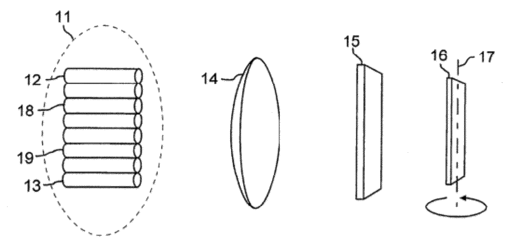
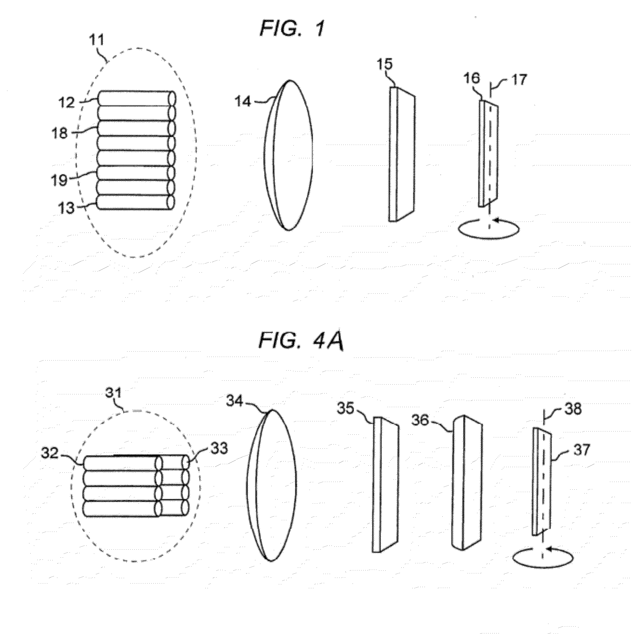
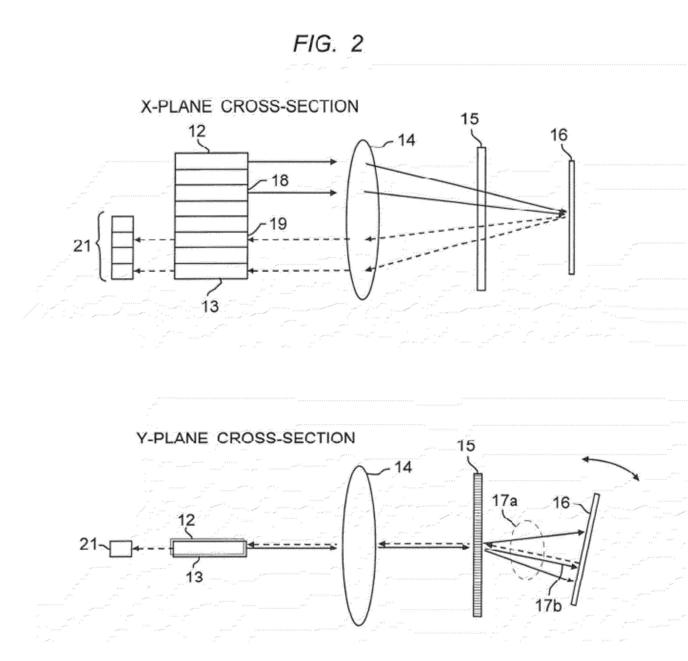
[0026]FIG. 1 shows a tunable multiport optical filter with an array of input and optical fibers shown at 11, and with collimating lens 14, dispersive element 15, and tuning mirror 16. The tuning mirror rotates around axis 17. It should be understood that this figure (and subsequent figures) is not drawn to scale. Optical elements are located and spaced according to their functions and properties as known in the art. The description herein uses x- and y- axial notations for directions around the z-axis, which is the direction of light propagation through the device. Reference herein to the x-plane or the y-plane will be understood to mean the x-z or y-z planes. Reference in the figures to the x-axis cross section or the y-axis cross section is intended to mean a view of the x-z plane or the y-z plane respectively.
[0027]The embodiments shown are described in the context of OPM applications. However, it should be understood that the basic devices described herein are also useful as wav...
second embodiment
[0043]The fiber array may have other formats, one of which is illustrated in FIGS. A and 4B. FIG. 4A is a perspective view showing a tunable multiport optical filter. FIG. 4B is a schematic illustration of the operation of the tunable multiport optical filter of FIG. 4A, showing ray diagrams for the x- and y-directions of the device. In FIGS. 4A and 4B, a fiber array 31 is arranged in a 2×4 format to achieve a 4-port tunable filter. FIGS. 4A and 4B also show a different optical configuration. In the system of FIGS. 4A and 4B, two lenses are used. The first lens, 34, is a spherical or aspherical lens used to collimate the beam in both x- and y-directions. The second lens, 36, is a cylindrical lens. It focuses the input beam from input optical fiber 32 in the y-direction but does not focus the beam in x-direction. In this optical configuration, the returning light beam returns to the associated output optical fiber 33 with the same y-direction coordinates. The tunable multiport optica...
PUM
 Abstract
Description
Claims
Application Information
 - R&D
- Intellectual Property
- Life Sciences
- Materials
- Tech Scout
- Unparalleled Data Quality
- Higher Quality Content
- 60% Fewer Hallucinations
Browse by: Latest US Patents, China's latest patents, Technical Efficacy Thesaurus, Application Domain, Technology Topic, Popular Technical Reports.
© 2025 PatSnap. All rights reserved.Legal|Privacy policy|Modern Slavery Act Transparency Statement|Sitemap|About US| Contact US: help@patsnap.com


