Apparatus and method for measuring the internal pressure of an examination object

a technology of internal pressure and apparatus, applied in the field of apparatus and a method for measuring the internal pressure of an examination object, can solve the problems of pulmonary artery pressure that cannot be reliably measured, complications that can be life-threatening, and other problems, and achieve the effect of not presenting a serious risk to the patient and being convenient to apply

Active Publication Date: 2012-06-28
KONINKLIJKE PHILIPS ELECTRONICS NV
View PDF4 Cites 6 Cited by
  • Summary
  • Abstract
  • Description
  • Claims
  • Application Information

AI Technical Summary

Benefits of technology

[0011]It is an object of the present invention to provide an improved apparatus and method for non-invasively measuring the internal pressure of an examination object, in particular the internal pressure of a blood vessel, which are, compared to methods known in the art, more accurate, easier to apply and which do not present a serious risk for the patient.

Problems solved by technology

Unfortunately, the pulmonary artery pressure can only be measured reliably using an expensive catheter procedure.
Unfortunately, this procedure is due to its invasive complicated character not at all without risk, and complications can be live threatening.
It can lead to arrhythmias, rupture of the pulmonary artery, thrombosis, infection, pneumothorax, bleeding, and other problems.
Of course, other indirect methods like arterial gas levels and ultrasound are known to measure the pressure in the pulmonary arteries, but they just give a valuable insight into the disease, but no definitive answer.

Method used


Image

  • Apparatus and method for measuring the internal pressure of an examination object
  • Apparatus and method for measuring the internal pressure of an examination object
  • Apparatus and method for measuring the internal pressure of an examination object

Examples


embodiment 10

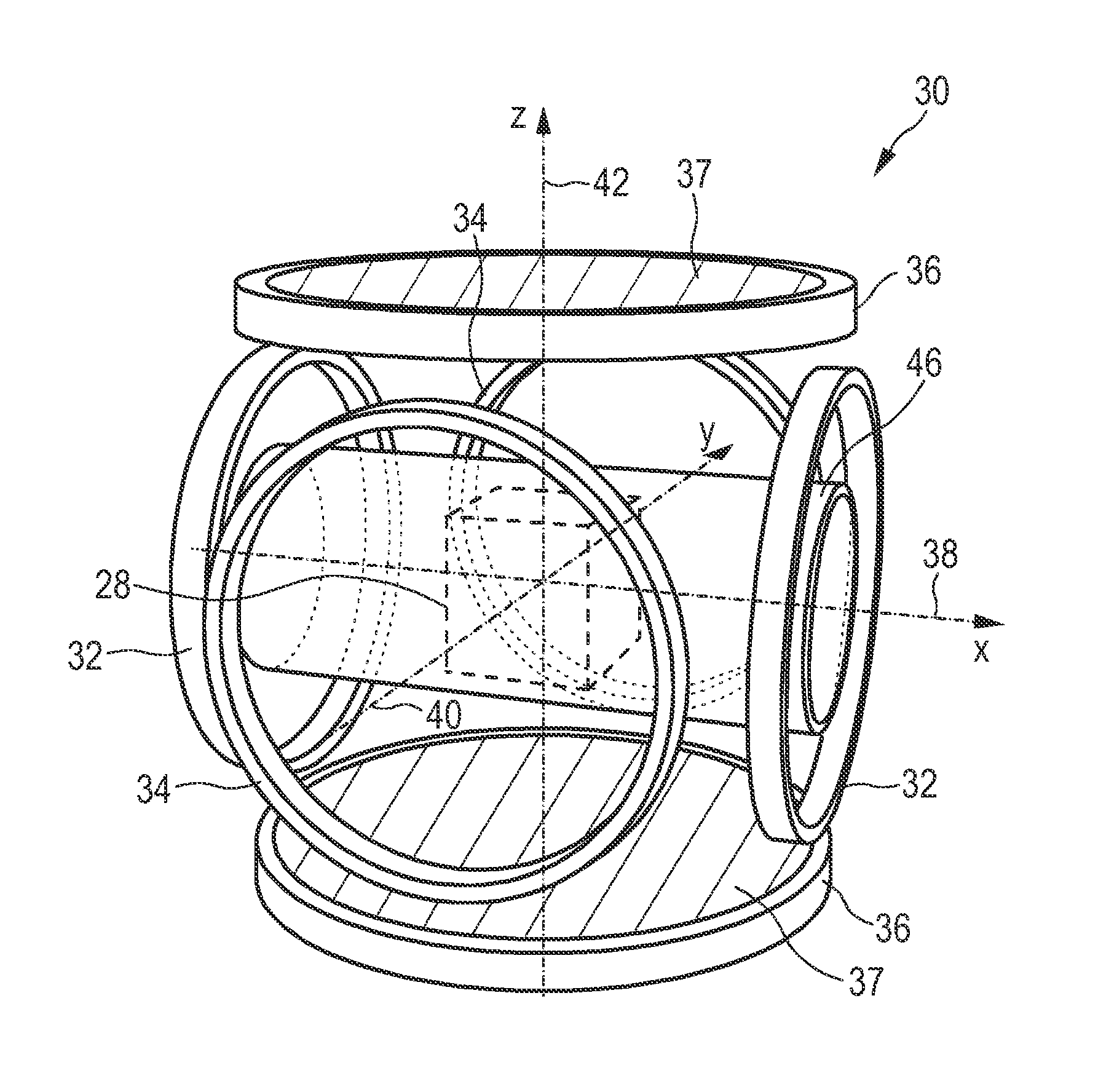
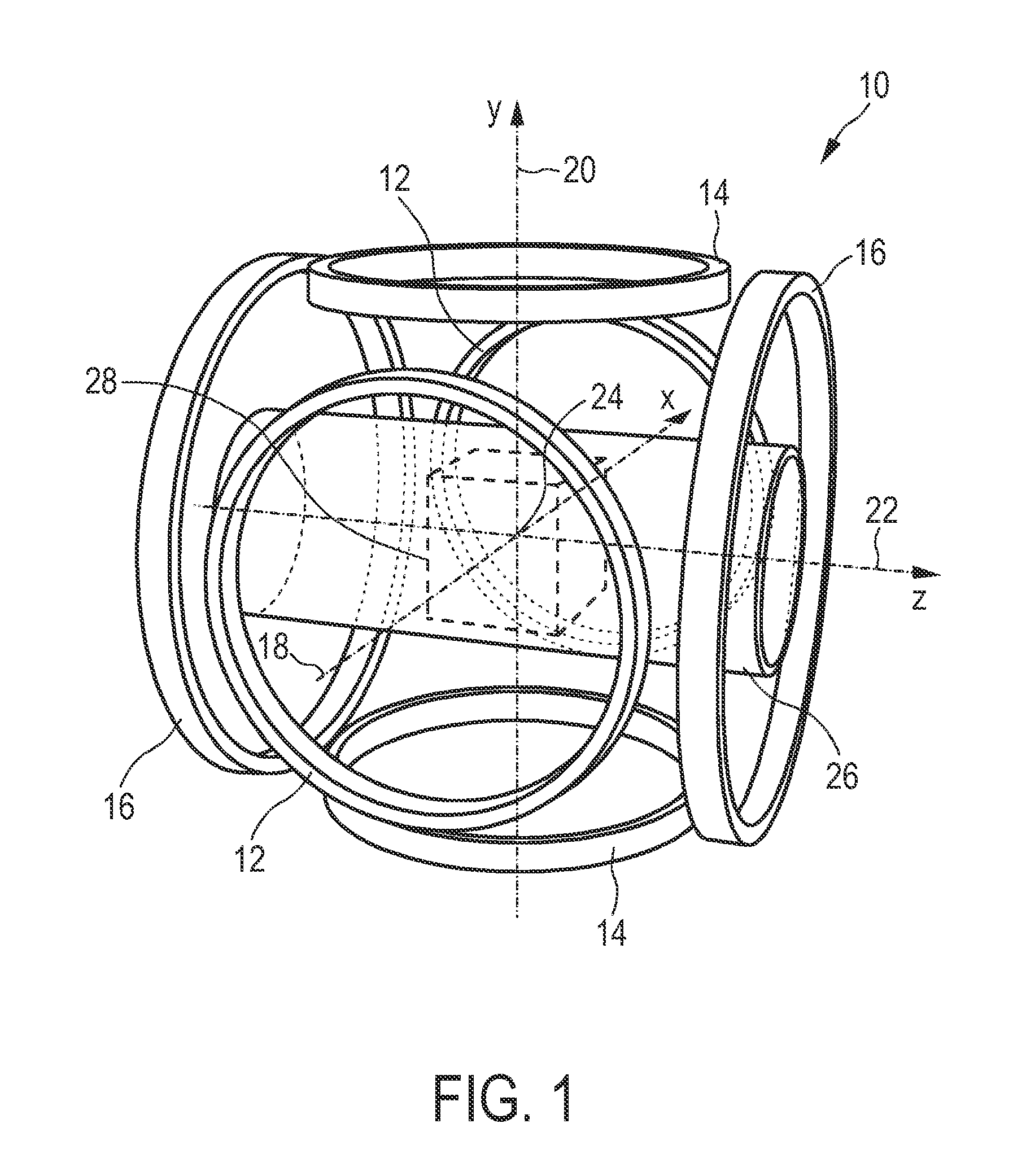
[0080]The embodiment 10 of the MPI scanner has at least one further pair, preferably three further pairs, of parallel circular coils, again oriented along the x-, y-, and z-axes. These coil pairs, which are not shown in FIG. 1, serve as receive coils. As with the coil pairs 12, 14, 16 for the drive and focus fields, the magnetic field generated by a constant current flowing through one of these receive coil pairs is spatially nearly homogeneous within the field of view and parallel to the axis of the respective coil pair. The receive coils are supposed to be well decoupled. The time dependent voltage induced in a receive coil is amplified and sampled by a receiver attached to this coil. More precisely, to cope with the enormous dynamic range of this signal, the receiver samples the difference between the received signal and a reference signal. The transfer function of the receiver is non-zero from DC up to the point where the expected signal level drops below the noise level.

[0081]T...

first embodiment

[0095]The major elements of the apparatus shown in FIG. 4 are magnetic field generating means 130, 136, receiving means 140, 148 and evaluation means 153. The functions of these means shall be explained in an MPI mode in the following.

[0096]For generating a magnetic field for influencing the magnetization of the magnetic pressure measurement device 60, 70 the apparatus 100 comprises magnetic field generating means which itself comprise a subset of magnetic field coils, preferably three pairs 136a, 136b, 136c of oppositely arranged magnetic coil elements. These magnetic field coils 136a, 136b, 136c are controlled by a magnetic field signal generator unit 130, preferably comprising a separate magnetic field signal generation subunit for each coil element (or at least each pair of coil elements) of said set of magnetic field coils 136a, 136b, 136c. Said magnetic field signal generator unit 130 comprises a magnetic field current source 132 (preferably including a current amplifier) and ...

second embodiment

[0107]As already mentioned above, the apparatus 100 according to the present invention further comprises focus means. These focus means comprise a set of focus field (FF) coils, preferably three pairs 126a, 126b, 126c of oppositely arranged focus field coil elements. Set magnetic focus field is generally used for changing the position in space of the field of view 28. The focus field coils are controlled by a focus field signal generator unit 120, preferably comprising a separate focus field signal generation subunit for each coil element (or at least each pair of coil elements) of said set of focus field coils. Said focus field signal generator unit 120 comprises a focus field current source 122 (preferably comprising a current amplifier) and a filter unit 124 for providing a focus field current to the respective coil of said subset of coils 126a, 126b, 126c which shall be used for generating the magnetic focus field. The focus field signal generator unit 120 is also controlled by ...


PUM


Abstract

The present invention relates to an apparatus (100) for measuring the internal pressure of an examination object, in particular the internal pressure of a blood vessel, by use of a magnetic pressure measurement device (60, 70) introduced into the examination object, which apparatus comprises:—magnetic field generating means comprising magnetic field signal generator units (130) and magnetic field coils (136a, 136b, 136c) for generating a magnetic field for influencing the magnetization of the magnetic pressure measurement device (60, 70), receiving means comprising at least one signal receiving unit (140) and at least one receiving coil (148) for acquiring detection signals, which detection signals depend on the changes in magnetization of the magnetic pressure measurement device (60, 70) caused by the magnetic field and on the changes of the physical properties of the magnetic pressure measurement device caused by the internal pressure of the examination object, and evaluation means (153) for evaluating the detection signals of the magnetic pressure measurement device (60, 70) for determining the internal pressure of the examination object.

Description

FIELD OF THE INVENTION[0001]The present invention relates to an apparatus and a method for measuring the internal pressure of an examination object, in particular the internal pressure of a blood vessel, by use of a magnetic pressure measurement device introduced into the examination object. Further, the present invention relates to such a magnetic pressure measurement device for the use in such an apparatus. Still further, the present invention relates to a computer program for implementing said method on a computer and for controlling such an apparatus.BACKGROUND OF THE INVENTION[0002]The internal pressure measurement of blood vessels, in particular the internal pressure measurement in lung arteries plays a decisive role in modern medicine. The pressure measurement of pulmonary arteries is an important quantity for lung and heart function assessment. This pressure measurement in pulmonary arteries is used for the diagnosis of shock states, primary pulmonary hypertension, pulmonary...

Claims


Application Information

Patent Timeline
Patent Type & Authority Applications(United States)
IPC IPC(8): A61B5/0215
CPCA61B5/02007A61B5/0515A61B5/05A61B5/021
Inventor GLEICH, BERNHARDSCHMALE, INGO
Owner KONINKLIJKE PHILIPS ELECTRONICS NV
Why Eureka
Try Eureka