Semi-active snowmobile rear suspension

a suspension system and snowmobile technology, applied in snowmobiles, cycle equipment, instruments, etc., can solve the problems of unfavorable rider comfort levels, unfavorable device effect of reducing unsprung mass, and inability to adjust, etc., to achieve the effect of improving the motion ratio, increasing the force/displacement character, and constant motion ratio

Inactive Publication Date: 2012-06-28
MAGNA INTERNATIONAL INC
View PDF10 Cites 14 Cited by
  • Summary
  • Abstract
  • Description
  • Claims
  • Application Information

AI Technical Summary

Benefits of technology

[0015]To address the problem of falling rate suspension force/displacement design, the present invention uses a combination of bell crank and links to improve the motion ratio between the actual shock (or linear force device) and the vertical displacement of the suspension assembly with respect to the chassis. With the use of linkages and the angle at which the variable linear force device is mounted, a rising rate force/displacement characterisitc is obtained. This is achieved with either linear rate steel coil springs or the use of a compressed air force device with an onboard air compressor to change the spring rate of the air spring itself. Any combination of air springs, or coil springs when attached and used with the linkage system produces a variable rising rate suspension.
[0016]Typical suspensions today have motions ratios that are not constant t

Problems solved by technology

This produces unfavorable rider comfort levels when attempting to tune a suspension system with a single combination of spring and damping rates to be comfortable when traveling over low or smaller bumps, while being able to absorb high or deep level terrain.
Due to the difficulty involved in making adjustments, and the operator's abiltity to quantify or realize the improvement (or lack thereof) because the snowmoble must be stopped in order to perform the tasks, this often results in the situation where the rider is either too inconvienced to make changes, or doesn't readily feel the differences when adjustments are made.
The first mentioned device does not offer any improvement to reducing unsprung mass and is very prone to failure due to freezing of

Method used


Image

  • Semi-active snowmobile rear suspension
  • Semi-active snowmobile rear suspension
  • Semi-active snowmobile rear suspension

Examples


Embodiment Construction

[0045]The following description of the preferred embodiment(s) is merely exemplary in nature and is in no way intended to limit the invention, its application, or uses.

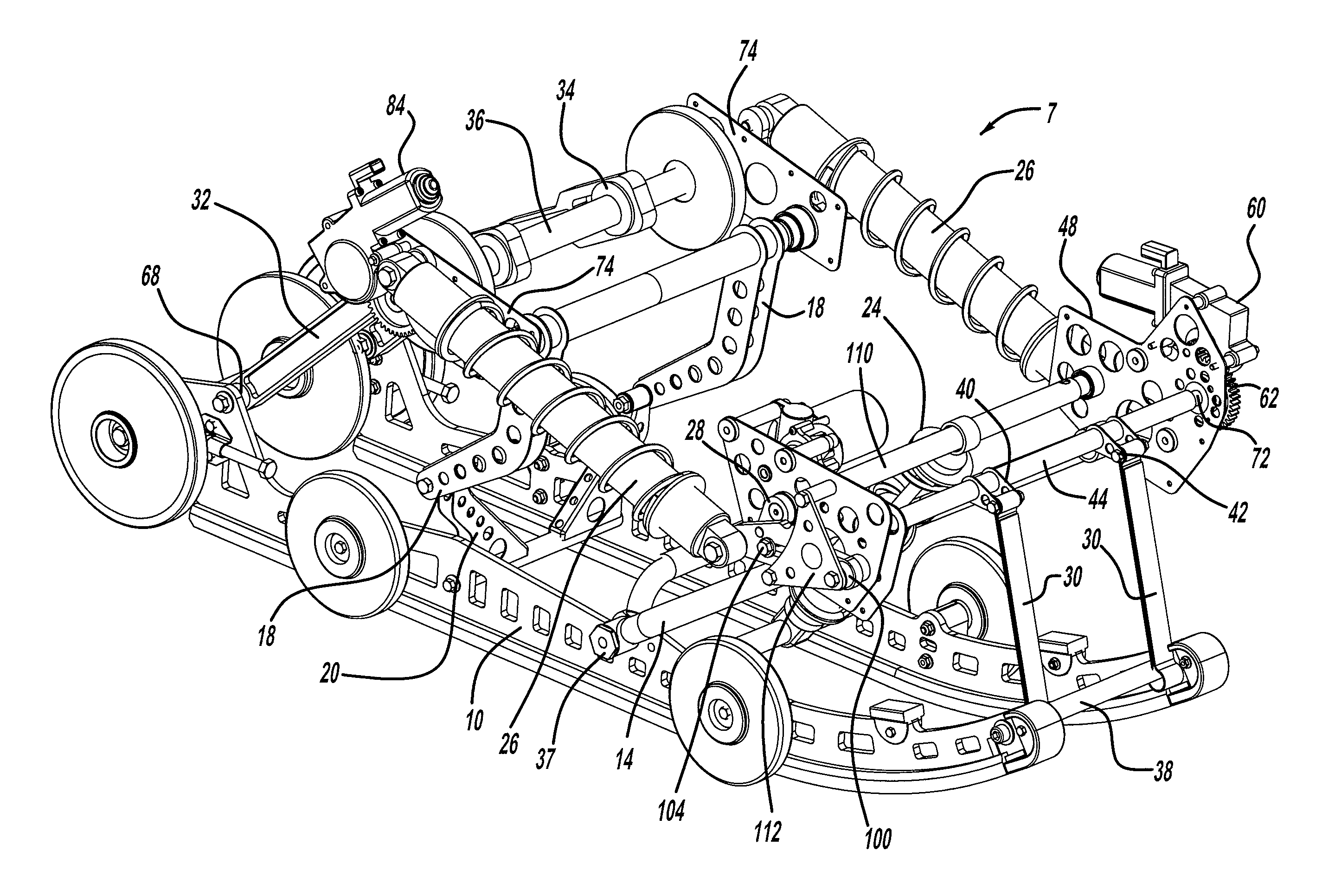
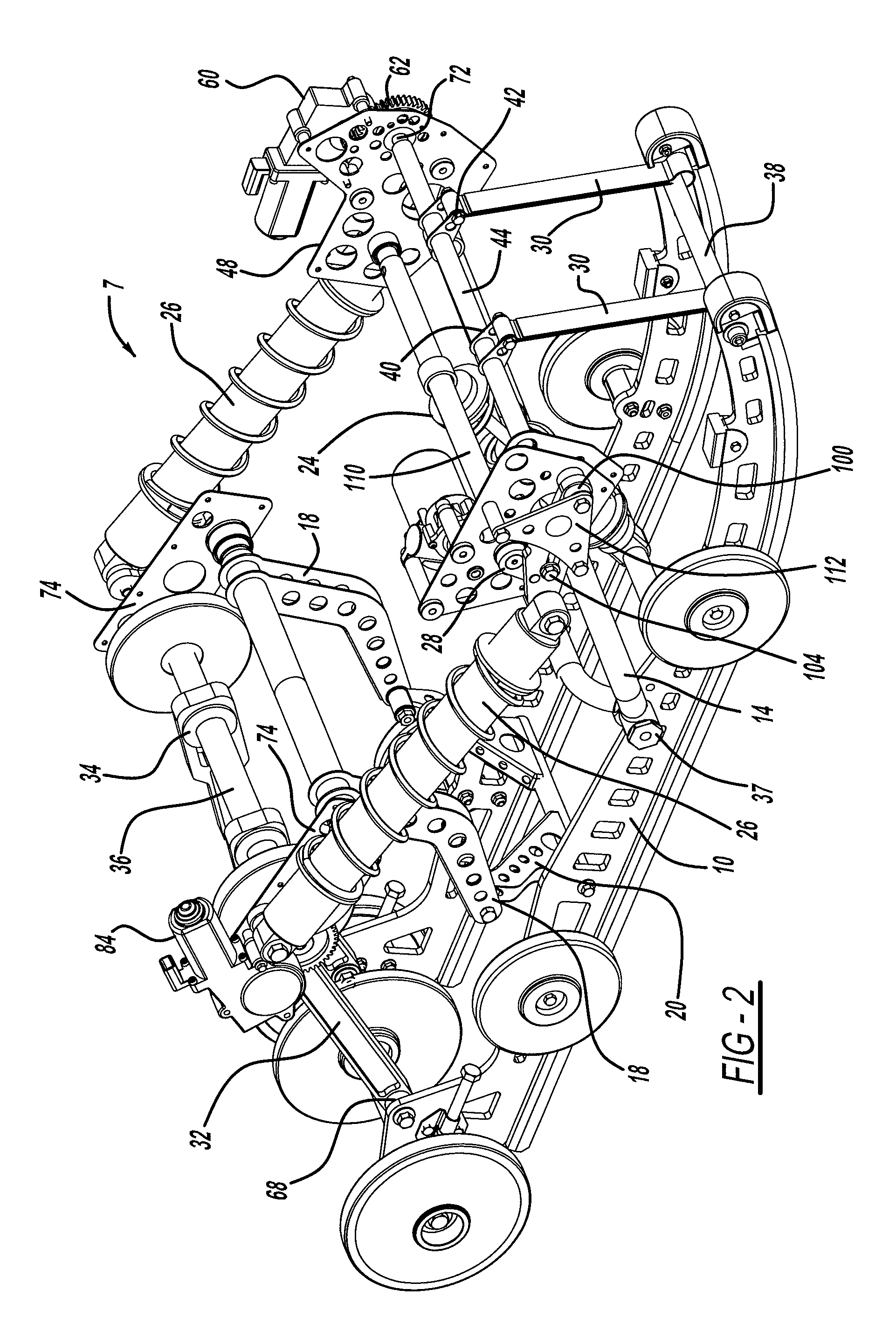
[0046]In some of the drawings contained herein some components of a snowmobile such as the track, front drive axle assembly have not been included in the figures for the sake of clarity as they are common and typical to most snowmobile rear suspension systems.

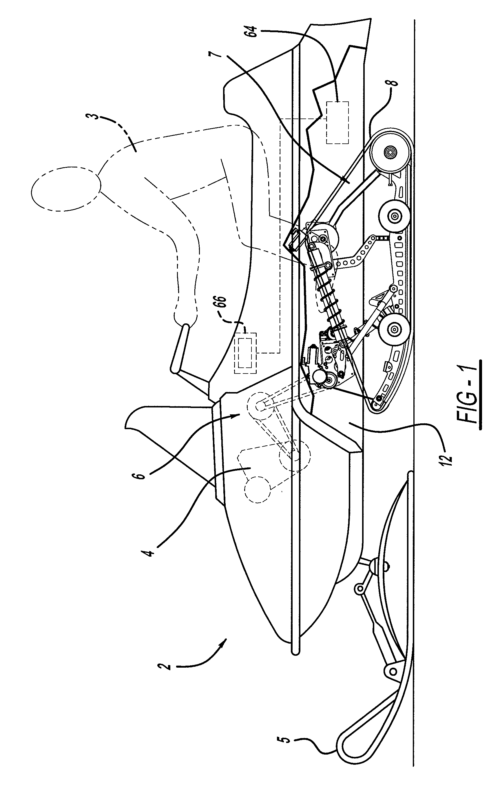
[0047]Referring now to FIG. 1 a side environmental view of a snowmobile having a suspension is shown in accordance with one embodiment of the present invention. A snowmobile 2 is generally depicted with a driver 3 seated thereon. The snowmobile has a skis 5 and a track 8 that contact the ground. The skis 5 are used for steering the snowmobile 2, while the track 8 is generally used to drive the snowmobile 2. The snowmobile 2 has an engine that supplies power to the track 8 through a drive mechanism 6. The drive mechanism 6 can be any suitable linkage including bel...


PUM


Abstract

A snowmobile suspension system connected between a skid frame positioned below a chassis of a snowmobile. A limiter strap adjustment mechanism is connected between the chassis and the at least one limiter strap and selectively adjusts the length of the at least one limiter strap. A coupling arm adjustment mechanism is connected between the chassis and at least one coupling arm and selectively adjusts the length of the at least one coupling arm. A linear force device adjustment mechanism is connected between the chassis and the linear force device for adjusting the length and angle of the linear force device relative to the at least one rear arm resulting in control of the force displacement characteristics of the at least one rear arm.

Description

CROSS-REFERENCE TO RELATED APPLICATIONS[0001]This application claims the benefit of U.S. Provisional Application No. 61 / 459,984, filed Dec. 22, 2010.FIELD OF THE INVENTION[0002]The present invention relates to a suspension system for a snowmobile which has a reduced amount of unsprung mass, improving the overall performance of the snowmobile and an electronically and manually adjustable suspension.BACKGROUND OF THE INVENTION[0003]Typical suspension designs for snowmobiles have relatively high unsprung weight values for the components due to the fact that most, if not all, components are arranged within the confines of the track perimeter and move when the suspension deflects vertically. In current snowmobile designs, as much as seventy percent of the weight of the snowmobile is unsprung weight. In addition, prior art systems have what is referred to as falling rate or constant rate spring force / vertical travel characterisitcs. This produces unfavorable rider comfort levels when atte...

Claims


Application Information

Patent Timeline
IPC IPC(8): B60G17/015B60G17/00
CPCB60G2300/322B60G17/015
Inventor WATSON, BRADLEY E.
Owner MAGNA INTERNATIONAL INC
Why Eureka
Try Eureka