Method for gasifying solid fuel with unified gas purification and gasifier using said method

a gasification and solid fuel technology, applied in the field of gasification solid fuel, can solve the problems of deteriorating gasification efficiency of fuel, lowering the purity and heat quantity of product gas, etc., and achieve the effect of high efficiency and high quality

Active Publication Date: 2012-07-05
IHI CORP
View PDF4 Cites 3 Cited by
  • Summary
  • Abstract
  • Description
  • Claims
  • Application Information

AI Technical Summary

Benefits of technology

[0046]According to the method for gasifying solid fuel with unified gas purification in the first aspect of the invention, the whole process of gasifying the solid fuel is divided into three phases of pyrolysis gasification, char combustion and gasified gas purification. Tar in the gasified gas generated by the pyrolysis gasification of the solid fuel is reformed in the gasified gas purification at the high reaction temperature in said gasified gas purification by the active chemical. The active chemical functioning as a catalyst to reform the tar is circulated together with the heat medium to the pyrolysis gasification where, at the low or medium temperature in said pyrolysis gasification, CO2 in the gasified gas is absorbed by the same active chemical. Further, in the char combustion, the heat medium is heated and the low-active and newly added inactive chemicals are calcined to be activated. As a result, by the active chemical which is circulated, CO2 in the gasified gas can be sufficiently absorbed at a proper reaction temperature in the pyrolysis gasification and tar in the gasified gas can be sufficiently reformed at a proper reaction temperature in the gasified gas purification; and, in the char combustion, the low-active and inactive chemicals can be sufficiently activated before contribution to tar reformation.
[0047]In short, in the respective phases of pyrolysis gasification, char combustion and gasified gas purification, the reaction temperatures can be independently controlled for realization of maximum reaction performances, so that the action of accelerating the gasifying reaction through absorption of CO2 in the gas by the chemical can be made compatible with the catalytic action of reforming the tar in the gasified gas generated by the gasifying reaction.
[0048]Thus, the gasification of the solid fuel can be realized at high efficiency and cleanly to obtain the gasified gas with high quality.
[0049]In the first reactor for pyrolysis gasification, suitable for the absorption reaction of O2 in the gasified gas by the active chemical, the reaction temperature in said first reactor can be maintained to the low or medium temperature of 773-1073 K at which CO2 in the gasified gas can be satisfactorily absorbed by the active chemical, so that even if the reactor of pyrolysis gasification phase is not at high pressure but substantially at normal pressure, CO2 in the gasified gas generated by the gasification can be reliably absorbed by the active chemical.
[0050]In the second reactor for char combustion, suitable for the re-activation and activation reactions of the low-active and inactive chemicals, respectively, the reaction temperature can be maintained to high temperature of 1073 K or more, so that the temperature of heat medium and active chemical can be sufficiently raised and the active chemical can be sufficiently activated.
[0051]In the third reactor for gasified gas purification, suitable for exhibition of the catalytic function of the active chemical to the tar reforming reaction, the reaction temperature in said gasified gas purification can be maintained to high temperature of 1073 K or more at which tar in the gasified gas can be satisfactorily reformed by the active chemical, so that the tar in the gasified gas can be reliably reformed by the active chemical and at the same time H2S, HCl and the like can be satisfactorily removed. In this case, owing to the more or less endotherm of the tar reforming reaction in said phase, the high reaction temperature in said gasified gas purification is somewhat lower than the reaction temperature in the char combustion, i.e., the temperature of the particles and active chemical heated in the char combustion, but can be reliably higher than the low or medium reaction temperature in the first reactor for pyrolysis gasification for said pyrolysis gasification.

Problems solved by technology

However, such combustion of the solid fuel itself disadvantageously deteriorates gasification efficiency of the fuel.
To carry out the combustion and gasification of the fuel in one and the same reaction space or gasification furnace inevitably causes a large amount of inert gases such as CO2 and N2 to be admixed in the gasified gas, resulting in lowering in purity and heat quantity of the product gas.
Moreover, the gas gasified in the high-temperatured environment is rich in CO and CO2 and poor in H2; in order to produce H2-enriched product gas required, for example, for a synthesizing process of GTL (Gas to Liquid), the high-temperatured gasified gas must be cooled to independently carry out CO shift reaction and removal of CO2.

Method used


Image

  • Method for gasifying solid fuel with unified gas purification and gasifier using said method
  • Method for gasifying solid fuel with unified gas purification and gasifier using said method
  • Method for gasifying solid fuel with unified gas purification and gasifier using said method

Examples


embodiment 1

[0082]First of all, a first embodiment will be described.

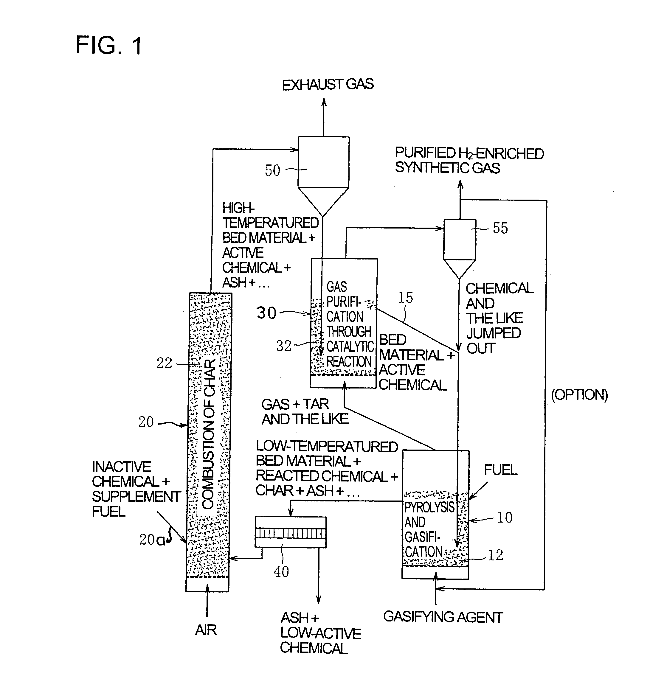
[0083]FIG. 1 shows schematic construction of a gasifier for solid fuel with unified gas purification according to the first embodiment of the invention. The description will be made in conjunction with FIG. 1.

[0084]The gasifier using the method for gasifying solid fuel with unified gas purification according to the invention is constructed as a system with an external circulation type fluidized bed, which separately comprises, as shown in FIG. 1, a gasification furnace (reactor for pyrolysis gasification) 10, a combustion furnace (reactor for char combustion) 20 and a gas purification furnace (reactor for gasified gas purification) 30, solid components being circulated through the furnaces 10, 20 and 30 together with fluid heat medium (bed material such as sand).

[0085]The gasification furnace 10 is a device with a fluidized bed 12 fed with solid fuel such as coal, biomass or various wastes and with a gasifying agent such as st...

embodiment 2

[0119]Next, a second embodiment will be described.

[0120]FIG. 7 shows schematic construction of a gasifier for solid fuel with unified gas purification according to the second embodiment of the invention. The description will be made in conjunction with FIG. 7. In this connection, explanation is omitted with respect to portions in common with the above-mentioned first embodiment.

[0121]In the second embodiment, the apparatus comprises a gasification furnace 10 and a gas purification furnace 30 which are vertically connected into an integral unit, calcined active chemical such as CaO and fluid heat medium being passed into the gasification furnace 10 through a particle pipage (particle passage) 15′ arranged in the furnaces 30 and 10.

[0122]Such integral construction of the gasification furnace 10 with the gas purification furnace 30 can make the whole of the apparatus compact in size and stabilize transfer of the fluid heat medium and active chemical such as CaO to the gasification furn...

embodiment 3

[0124]Next, a third embodiment will be described.

[0125]FIG. 8 shows schematic construction of a gasifier for solid fuel with unified gas purification according to the third embodiment of the invention. The description will be made in conjunction with FIG. 8. In this connection, explanation is made only on portions different from those in the above-mentioned second embodiment.

[0126]In the third embodiment, the apparatus comprises a gasification furnace 10 and a gas purification furnace 30 which are integrally constructed, a horizontal cross sectional area of the furnace 30 being larger than that of the furnace 10.

[0127]Such increased horizontal cross sectional area of the gas purification furnace 30 than that of the gasification furnace 10 prolongs dwell time of the product gas, which is generated in the gasification furnace 10, in the fluidized bed 32 of the gas purification furnace 30, so that the product gas is further satisfactorily purified during its passage through the furnace...


PUM

PropertyMeasurementUnit
temperatureaaaaaaaaaa
pressureaaaaaaaaaa
temperatureaaaaaaaaaa

Abstract

A gasification process is divided into three processes: a gasification furnace for carrying out gasification process by pyrolysis and gasification (pyrolysis gasification phase, first process), a combustion furnace for burning char to obtain calcined active chemical (char combustion phase, second process) and a gas purification furnace for purifying gasified gas (gasified gas purification phase, third process). Through heat transmission by the fluid heat medium and chemical reactions in respective phases by the chemical, the gasification furnace is independently controlled to a low or medium temperature (773-1073 K) which is required for gasification and which enables absorption of CO2; and the gas purification furnace is controlled to a high temperature (1073 K or more) required for gas purification.

Description

CROSS-REFERENCE TO RELATED APPLICATIONS[0001]This application is a division of U.S. patent application Ser. No. 11 / 916,365 filed Dec. 3, 2007, the entire contents of which is incorporated herein by reference. U.S. patent application Ser. No. 11 / 916,365 is a National Stage of PCT / JP06 / 305785 filed Mar. 23, 2006 and claims the benefit of priority from prior Japanese Patent Application No. 2005-195945 filed Jul. 5, 2005.TECHNICAL FIELD[0002]The present invention relates to technique for gasifying solid fuel, and more specifically relates to technique for gasifying solid fuel highly efficiently and more cleanly.BACKGROUND ART[0003]Gasification of solid fuel such as coal, biomass or various wastes in a gasification furnace is generally carried out in a high-temperatured environment of about 1123 K or more so as to obtain sufficient reaction speed and heat supply to the reaction. In order to attain such high-temperatured environment of about 1123 K or more in the gasification furnace, par...

Claims


Application Information

Patent Timeline
Patent Type & Authority Applications(United States)
IPC IPC(8): C10J3/72C10J3/00C10K1/26C10K1/30
CPCC10J3/463C10J3/54C10J3/66C10K1/20C10J2300/1823C10K1/026C10K3/023C10K3/04C10J2300/1807C10K1/26
Inventor KYO, KOUBUNMURAKAMI, TAKAHIROSUDA, TOSHIYUKIKUSAMA, SHIGERUFUJIMORI, TOSHIRO
Owner IHI CORP
Why Eureka
Try Eureka