
High frequency mode generator for radar level gauge

a high frequency mode and radar technology, applied in the direction of level indicators, measurement devices, instruments, etc., can solve the problems of difficult manufacturing of feeders, difficulty in forming thin plastic sheets, so as to achieve greater flexibility in design.

Active Publication Date: 2012-07-05
ROSEMOUNT TANK RADAR
View PDF4 Cites 35 Cited by
  • Summary
  • Abstract
  • Description
  • Claims
  • Application Information

AI Technical Summary

Benefits of technology

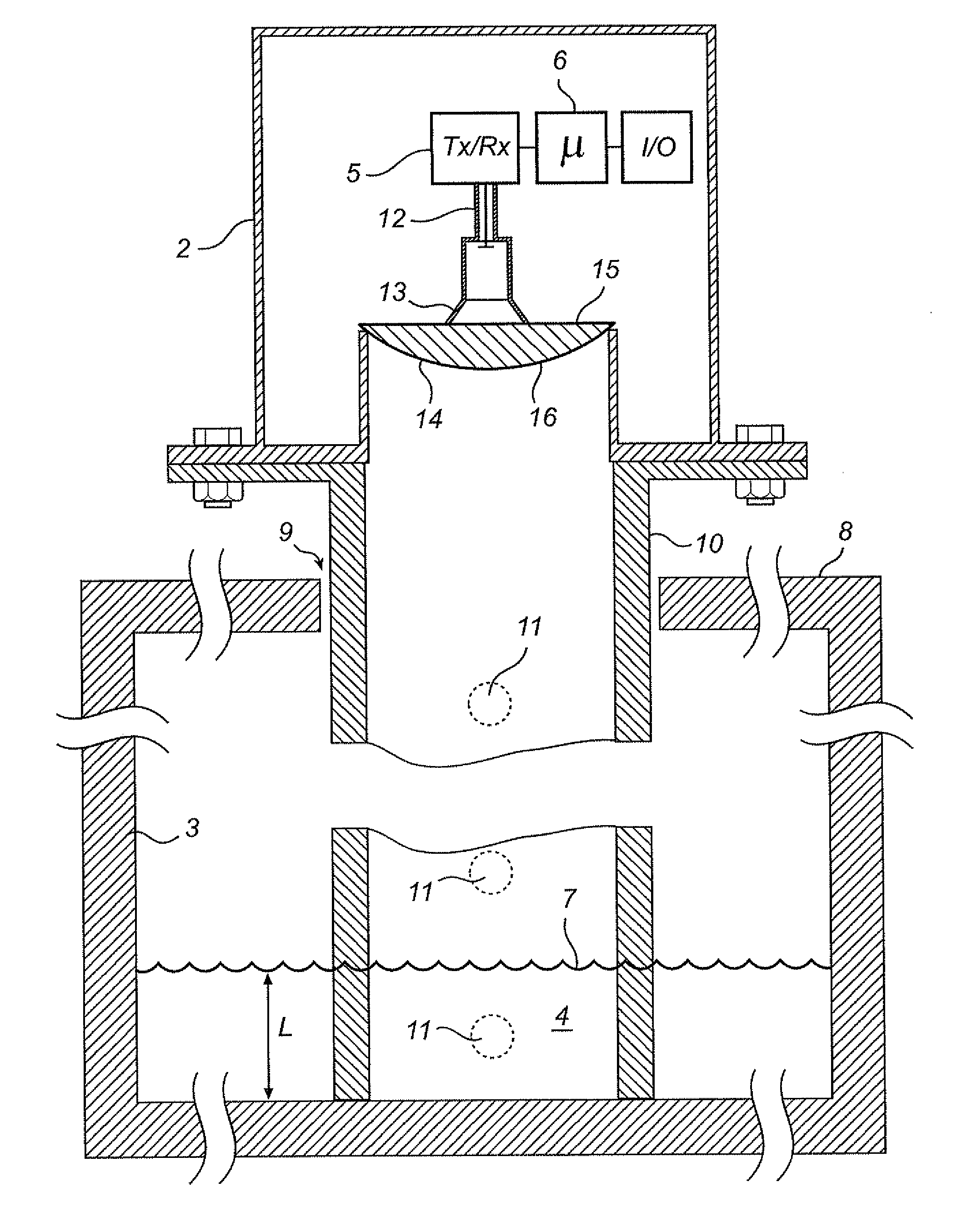
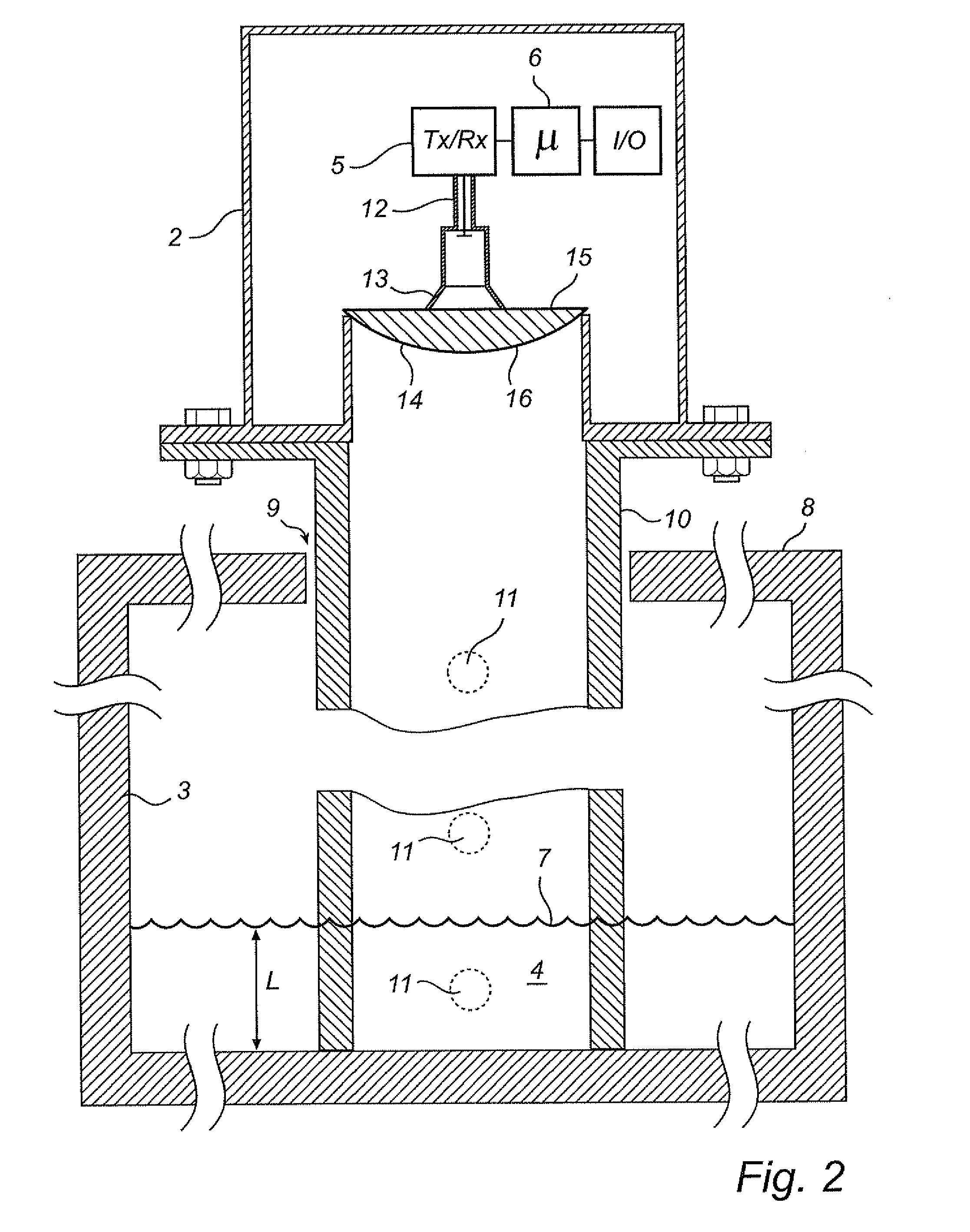
[0012]Compared to prior art solutions, where a focusing effect is created by one or two thin PCB:s manufactured non flat by heat forming (poly-ethylene PCB), the lens according to this aspect of the present invention is more stable for sub-mm accuracy, and also makes it easier to avoid undesired reflections. By making the mode generator in the form of a lens, problems with insufficient structural strength are also avoided effectively, especially in the case of a solid lens.
[0013]By using an optical element (lens), a focusing effect may be achieved not only by reflection, but also by refraction in a curved transition between mediums with different refraction index. For example, the bottom surface may be convex, and the refraction index of said lens greater than a surrounding medium, so that electromagnetic waves incoming from the tank parallel to the optical axis of the lens are refracted towards the optical axis when entering the lens. The incoming wave is then reflected by the upper surface, and a second time in the bottom surface.
[0015]A convex lower surface of the lens is further advantageous for avoiding remaining condensation on this surface.
[0017]However, a substantially flat upper surface is most likely advantageous from a manufacturing perspective. For example, a substantially flat upper surface makes it possible to implement the spiral pattern using a conventional process for printed circuit boards, such as etching. This provides greater flexibility in designing the spiral twist pattern as well as the feeding structure (radiator) in its center.

Problems solved by technology

In some applications the tank may contain interior structures causing disturbing reflections.
However, for high frequencies, such a feeder becomes difficult to manufacture due to the extreme tolerances.
While providing several advantages, the solution according to U.S. Pat. No. 4,641,139 requires very small scale structuring of the curved surfaces, and especially the thin plastic sheets may be challenging to manufacture.
Further, the structural strength of the lower surface may represent a problem, and any movement in this surface will influence the accuracy of the gauge.

Method used


Image

  • High frequency mode generator for radar level gauge
  • High frequency mode generator for radar level gauge
  • High frequency mode generator for radar level gauge

Examples


Embodiment Construction

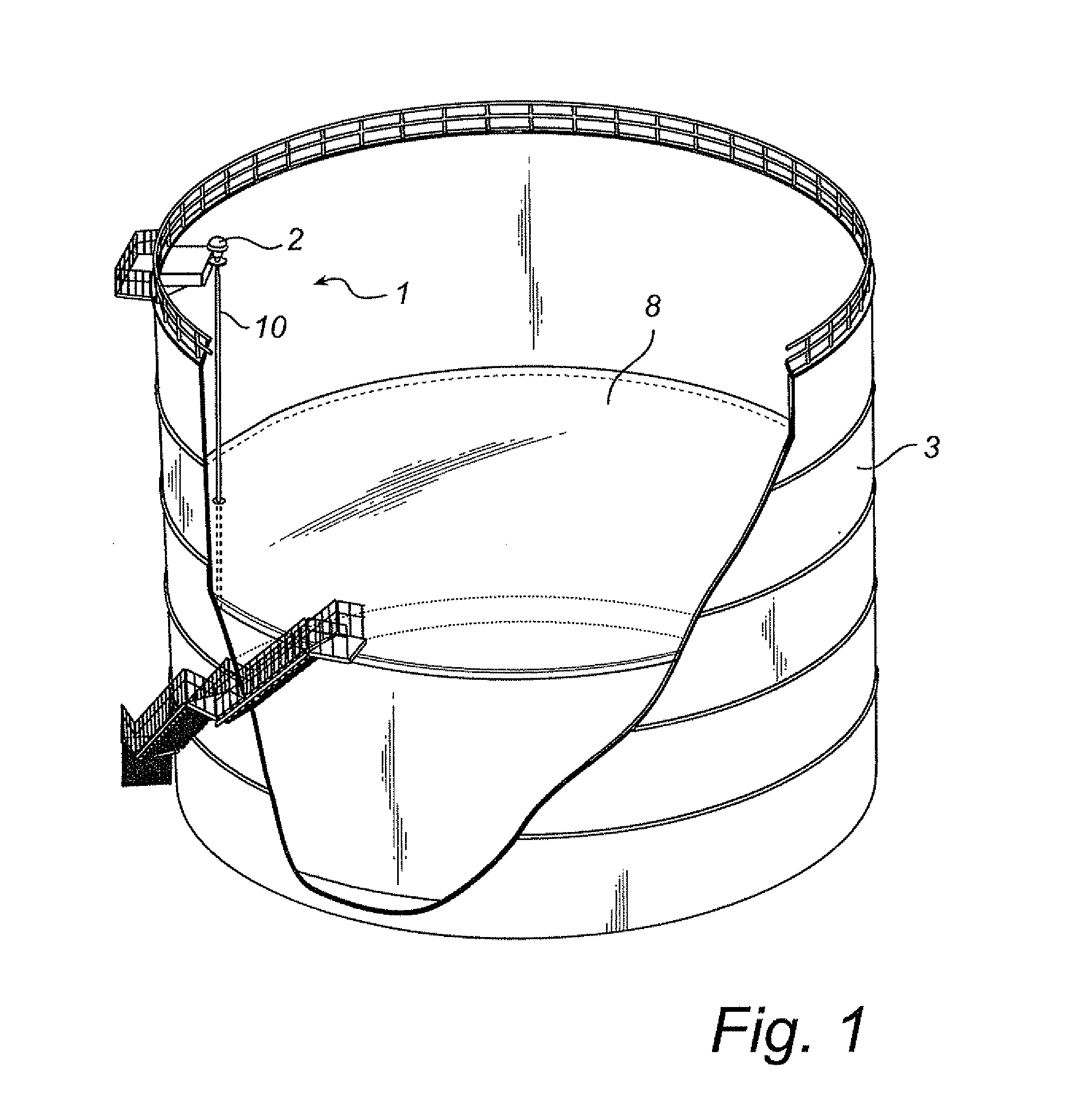
[0023]FIGS. 1 and 2 shows schematically a radar level gauge (RLG) system 1 according to an embodiment of the present invention. The RLG 1 comprises an electronics unit 2 mounted on a tank 3. The tank contains a liquid 4, which may be a petroleum product, such as crude oil or a product manufactured from it, or a condensed gas, which is stored in the container at overpressure and / or cooled. Propane and butane are two typical gases stored as liquids.

[0024]The unit 2 houses a transceiver 5, for transmitting a microwave signal and receiving a reflected microwave signal, and processing circuitry 6 for determining the distance to a reflecting surface 7 (or any other impedance transition) based on the transmitted signal and the reflected signal.

[0025]The system may be a frequency modulated continuous wave (FMCW) RLG system or a pulsed RLG system or any other type of distance measuring radar, but is preferably the former. The RLG system may have a capability of transmitting a microwave signa...


PUM


Abstract

A radar level gauging system for determining at least one process variable related to a distance to a surface of a product in a tank comprising transceiver circuitry, processing circuitry, a wave guiding structure arranged guide measurement signals towards the surface, and a radiator connected to the transceiver circuitry and arranged to emit the measurement signal into the wave guiding structure. The system further comprises a mode generator adapted to convert electromagnetic waves emitted from the radiator from a first propagation mode to a second propagation mode, wherein the mode generator includes a lens in the form of a body transparent to electromagnetic waves in the operating frequency range.With this design, electromagnetic waves having the first propagation mode emitted by the radiator into the lens will be reflected at least twice within the lens (first in the bottom surface and then in the upper surface). At the second reflection (in the upper surface of the lens), the propagation mode will be changed, and the electromagnetic waves exiting the lens will have the second propagation mode.

Description

FIELD OF THE INVENTION[0001]The present invention relates to a radar level gauging system of the kind having a wave guiding structure arranged to guide a measurement signal towards a surface in a tank and a high frequency mode generator.BACKGROUND OF THE INVENTION[0002]Radar level gauge systems for measuring the level of a liquid or other filling materials in a tank are well-known, and such a system generally comprises a transmitter for transmitting a microwave signal towards the surface of the liquid, a receiver for receiving the microwave signal reflected against the surface of the liquid, and a signal processing device for calculating the level of the liquid in the tank from the propagation time of the transmitted and reflected microwave signal. Such device has become more and more important, particularly for petroleum products such as crude oil and products manufactured from it. The tank may be a large container constituting parts of the total loading volume of a tank ship, or e...

Claims


Application Information

Patent Timeline
IPC IPC(8): G01S13/08G01S13/88
CPCG01F23/284
Inventor EDVARDSSON, OLOV
Owner ROSEMOUNT TANK RADAR
Learn More