Direct Ray Tracing of 3D Scenes

a technology of direct ray tracing and 3d scenes, applied in the field of computer graphics images of 3d, can solve the problems of nave ray tracing, millions of time slower than current approaches, and the trivial complexity of this algorithm, so as to accelerate the algorithm

Active Publication Date: 2012-07-05
IMAGINATION TECH LTD
View PDF6 Cites 29 Cited by
  • Summary
  • Abstract
  • Description
  • Claims
  • Application Information

AI Technical Summary

Benefits of technology

[0026]The present disclosure also presents an efficient way of storing the scene in memory, to perform in-place computations, pivot-based algorithms to stream rays and primitives, and for grouping rays into (conic) packets to accelerate the algorithm.

Problems solved by technology

However, the trivial complexity of this algorithm—O(primitives×rays)—is not suitable for most applications that nowadays handle large quantities of rays and primitives.
Indeed, naïve ray-tracing can be millions of time slower than current approaches when very large scenes with millions of primitives are handled.
This raises a few issues as extra construction time is likely to provide a better tracing rate, while faster construction times may see tracing times degrading.
However, some discrepancy in rendering times given by Lagae and Dutré is visible, and grids seem to perform noticeably worse for scenes with anisotropic triangles, as predicted by Ize et al.
A drawback to all previously mentioned approaches is that the memory footprint, i.e. the memory resources required, may vary between the frames, which is a disadvantage with regard to software engineering, as dynamic allocation should then be involved to optimize memory management on the system such that memory is only allocated when needed.
Instead, many approaches do not include the cost of dynamic allocation in their discussion and just make use of pre-allocated memory.
Nonetheless, Lagae and Dutré presented a framework for dynamic re-allocation with limited impact.
As mentioned above, all methods suggested so far make use of a compulsory additional data structure, such as the spatial subdivision data structure, which in RT is often seen as a burden by developers, and makes RT more complex.

Method used


Image

  • Direct Ray Tracing of 3D Scenes
  • Direct Ray Tracing of 3D Scenes
  • Direct Ray Tracing of 3D Scenes

Examples


Embodiment Construction

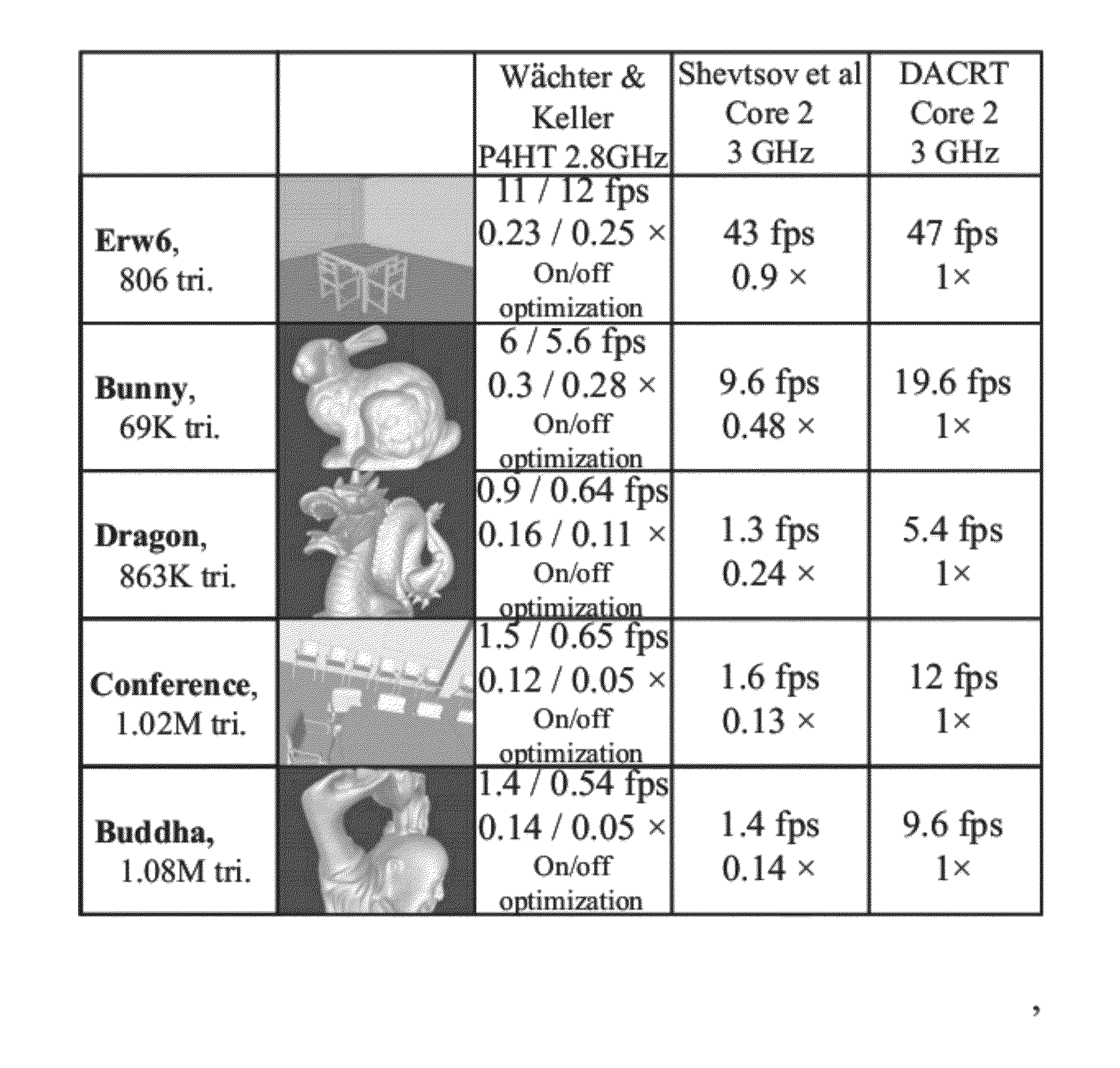
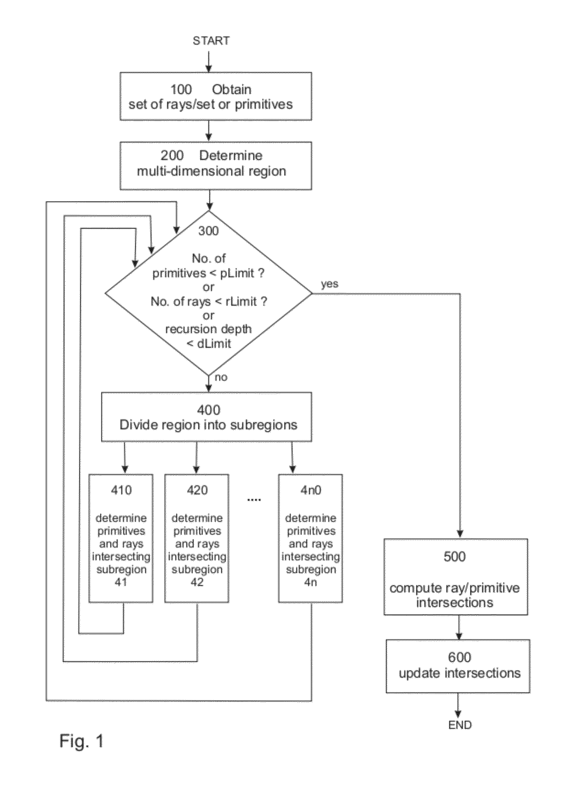
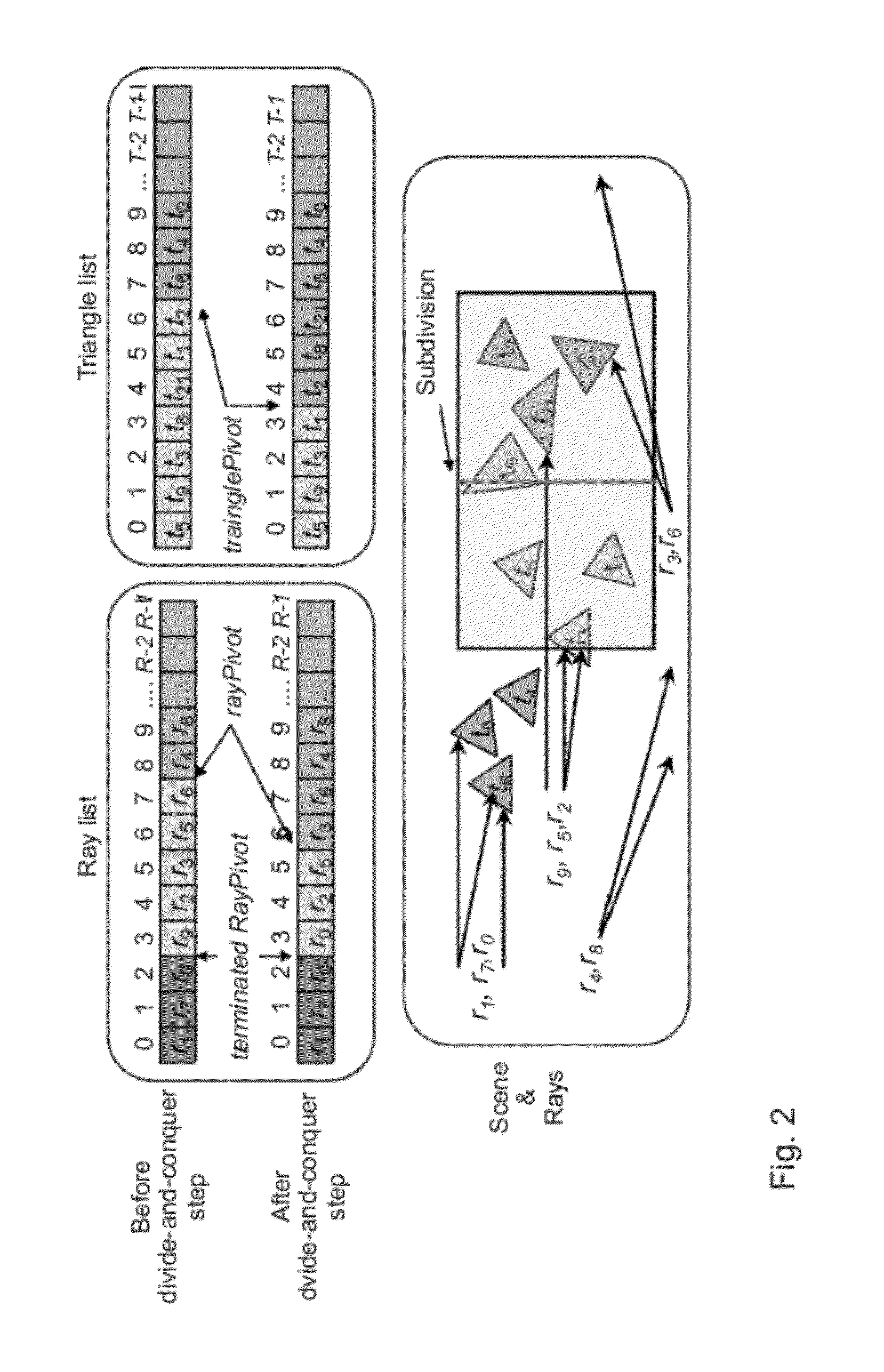
[0042]The naïve ray-tracing (naïve RT) algorithm comprises two nested loops computing every possible ray-triangle intersection in a scene at a complexity of O(primitives×rays). This naïve ray-tracing approach is processing far too many intersections. The present disclosure suggests simplifying the problem by only intersecting subsets of rays with subsets of triangles, which will be determined by a divide-and-conquer scheme using spatial subdivisions, as in the Algorithm 1:

Algorithm 1 Divide-And-Conquer Ray-Tracingprocedure DACRT( SpaceRegion E, SetOfRays R, SetOfPrimitives P)begin  if R.size   then NaiveRT ( R, T );  else begin    {Ei} = SubdivideSpaceRegion ( E )    for each Ei do      SetOfRays R′ = R ∩ Ei;      SetOfPrimitives P′ = P ∩ Ei;      DACRT ( Ei, R′, P′ );    end do  endend

[0043]This method is termed divide-and-conquer ray tracing (DACRT). The DACRT algorithm first compares—step 300—the number of primitives, which are triangles in the examples shown herein, and the numb...


PUM


Abstract

Determining intersections between rays and triangles is at the heart of most Computer Generated 3D images. The present disclosure describes a new method for determining the intersections between a set of rays and a set of triangles. The method is unique as it processes arbitrary rays and arbitrary primitives, and provides the lower complexity typical to ray-tracing algorithms without making use of a spatial subdivision data structure which would require additional memory storage. Such low memory usage is particularly beneficial to all computer systems creating 3D images where the available on-board memory is limited and critical, and must be minimized. Also, a pivot-based streaming novelty allows minimizing conditional branching inherent to normal ray-tracing techniques by handling large streams of rays. In most cases, our method displays much faster times for solving similar intersection problems than preceding state of the art methods on similar systems.

Description

CROSS-REFERENCE TO RELATED APPLICATIONS[0001]The present application is a continuation of PCT Application No. PCT / EP2009 / 059618 entitled “Direct Ray Tracing of 3D Scenes” and filed on Jul. 24, 2009.[0002]The aforementioned PCT patent application is hereby incorporated by reference in its entirety.BACKGROUND OF THE INVENTION[0003]1. Field of the Invention[0004]The present invention relates to the field of computer graphics images of 3D (three-dimensional) scenes or spaces. The present invention also relates to a method and a computer system for rendering computer graphics images using ray-tracing.[0005]2. Background of the Invention[0006]Ray-Tracing (RT) is a fundamental, much investigated and much used computer graphics algorithm for solving primitive / ray intersections, for example in displaying three dimensional objects and scenes on two-dimensional displays or screens. Primitives are used to describe the scene, while rays are used to model light paths. Unlike rasterization, RT can...

Claims


Application Information

Patent Timeline
Patent Type & Authority Applications(United States)
IPC IPC(8): G06T15/00
CPCG06T15/06
Inventor MORA, BENJAMIN
Owner IMAGINATION TECH LTD
Why Eureka
Try Eureka