Eureka AIR delivers breakthrough ideas for toughest innovation challenges, trusted by R&D personnel around the world.

Estimation of intentional phase shift in a calibration apparatus

Inactive Publication Date: 2012-07-05
QUALCOMM INC
View PDF4 Cites 8 Cited by
  • Summary
  • Abstract
  • Description
  • Claims
  • Application Information

AI Technical Summary

Benefits of technology

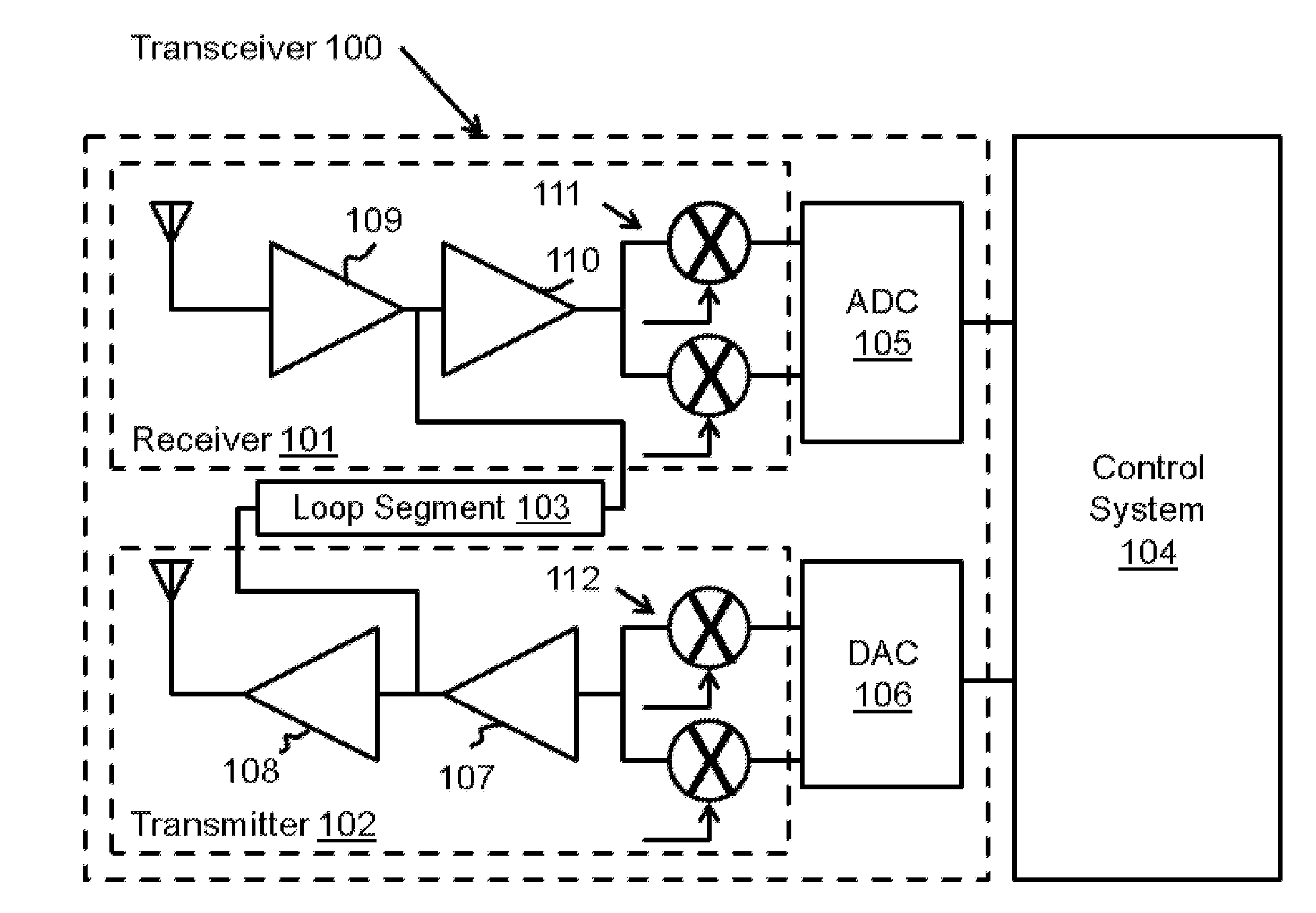
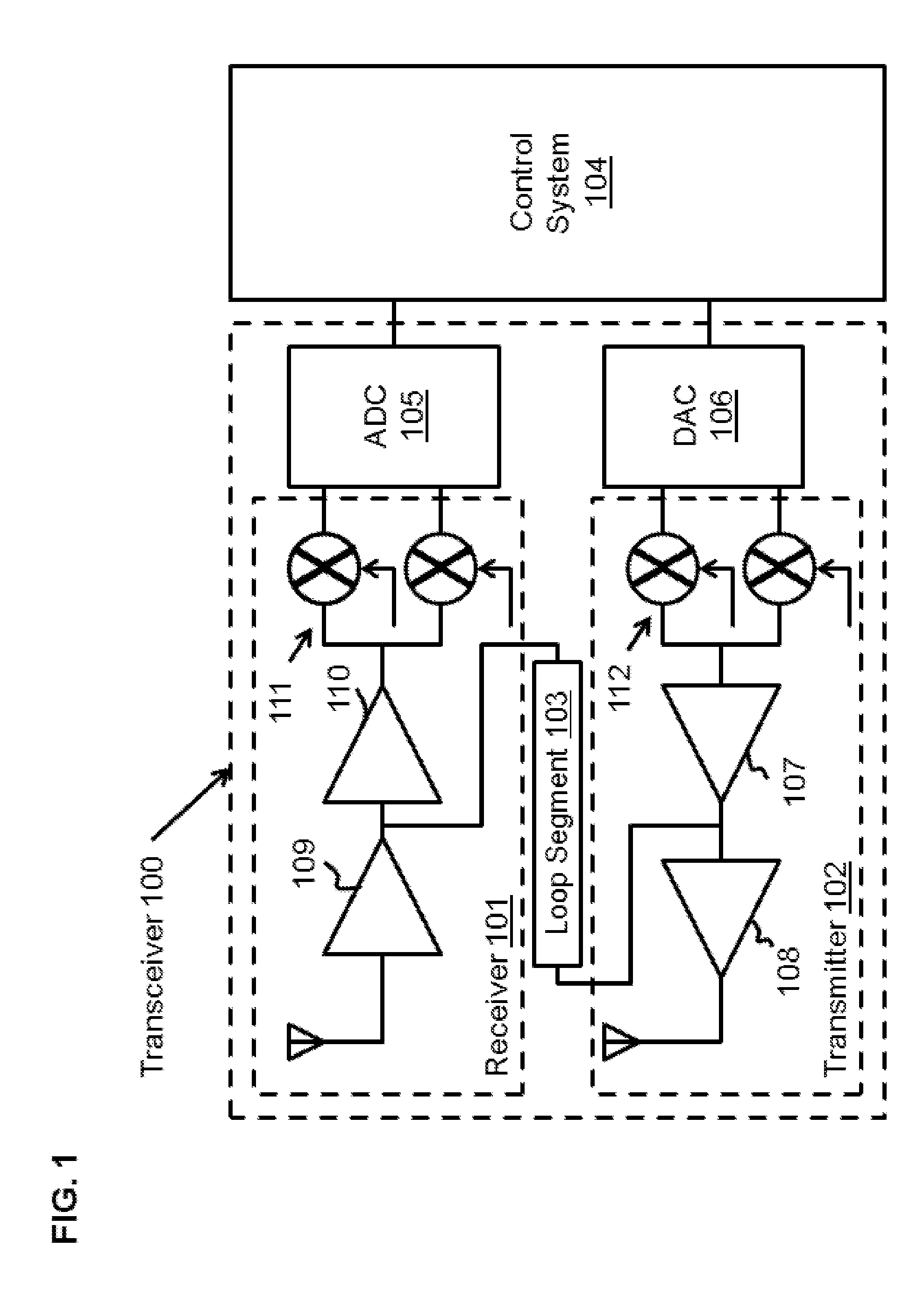
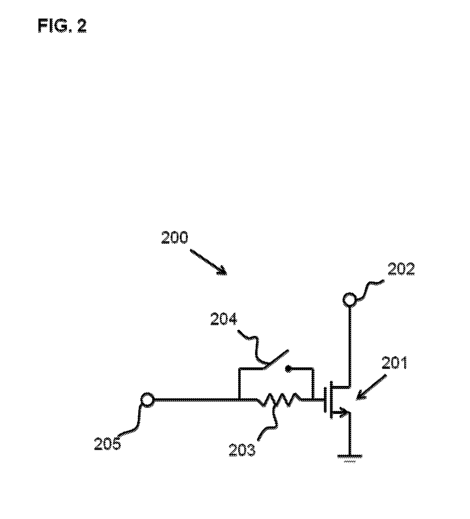
[0008]In another embodiment of the invention, a system is provided. The system comprises a transceiver having a receiver and a transmitter connected through a segment of a calibration loop back path. The system also comprises a control system configured to communicate with the transceiver. The system also comprises an IQ mismatch calibration unit that is within the control system, and a transmitter pre-distortion unit that is also within the control system. The transmitter pre-distortion unit is configured to provide a pre-distortion compensation. The calibration loop back path has an intentional phase shift that can b

Problems solved by technology

Precision is required because wireless signals are corrupted by noise as they are sent through a wireless medium and because as more complex patterns are used to represent information it becomes more challenging to determine one pattern from another.
Although I / Q channel modulation has certain benefits regarding the amount of bandwidth consumed, the increased complexity of the modulation scheme can result in several errors that make resolving the signal difficult.
Like other wireless systems, I / Q channel modulated signals can suffer from carrier leak.
In addition, I / Q channel modulated signals are susceptible to a group of errors that can collectively be referred to as IQ imbalance errors.
If the transmitter does not impart the right amount of phase shift, or the receiver resolves the signals as if they had a different phase shift, this mismatch will also bleed into the signal itself and will show up as an error in the signal.
This means that two parts that come off of the assembly line one after the other may have manufacturing imperfections that result in highly variant error metrics.
Therefore, a designer cannot design out these error sources and produce a design that will always work.

Method used


Image

  • Estimation of intentional phase shift in a calibration apparatus
  • Estimation of intentional phase shift in a calibration apparatus
  • Estimation of intentional phase shift in a calibration apparatus

Examples


Embodiment Construction

[0014]Reference will now be made in detail to embodiments of the present invention, examples of which are illustrated in the accompanying drawings. While the invention will be described in conjunction with these embodiments, it will be understood that they are not intended to limit the invention to these embodiments. On the contrary, the invention is intended to cover alternatives, modifications and equivalents, which may be include within the spirit and scope of the invention as defined by the appended claims. Furthermore, in the following detailed description of embodiments of the present invention, numerous specific details are set forth in order to provide a thorough understanding of the present invention. However, it will be recognized by one of ordinary skill in the art that the present invention may be practiced without these specific details. In other instances, well-known methods, procedures, components, and circuits have not been described in detail as not to unnecessarily...


PUM


Abstract

Embodiments of the present invention provide an apparatus comprising a transceiver having a receiver and a transmitter connected through a segment of a calibration loop back path. The apparatus also comprises a control system configured to communicate with the transceiver. The calibration loop back path has an intentional phase shift that can be toggled between an off state and an on state by the control system. The control system is configured to calculate the intentional phase shift by examining the difference of a first and second phase angle. The first phase angle is obtained from the transmission of a first pair of signals with the intentional phase shift in the off state. The second phase angle is obtained from the transmission of a second pair of signals with the intentional phase shift in the on state.

Description

FIELD OF THE INVENTION[0001]This invention relates to radio transceivers, and more specifically to methods and systems for calibrating radio transceivers.BACKGROUND OF THE INVENTION[0002]At the turn of the 20th century the airwaves of the United States were completely silent. Today they are filled to the brim with wireless communication signals. The recent history of wireless telegraphy is characterized by a concerted push towards fitting more and more information into the air. Complex modulation schemes have been developed that package information with increasing efficiency. To match this ever increasing degree of efficiency radios are required to resolve these signals with a commensurate degree of precision. Precision is required because wireless signals are corrupted by noise as they are sent through a wireless medium and because as more complex patterns are used to represent information it becomes more challenging to determine one pattern from another.[0003]Modulation schemes su...

Claims


Application Information

Patent Timeline
IPC IPC(8): H04B1/38
CPCH04L27/364H04L27/3854H04B1/62H04L2027/0022H04L2027/0016
Inventor LY-GAGNON, YANN
Owner QUALCOMM INC
Why Eureka
Eureka Blog
Learn More