Circuits, Architectures, Apparatuses, Systems, and Methods for Merging of Management and Data Signals, and for Recovery of a Management Signal

a management signal and circuit technology, applied in the field of optical and/or optoelectrical communication, can solve the problems of increasing the cost of the host system, reducing bandwidth, and increasing the complexity of the network structure, so as to reduce the cost, save network resources, and effectively improve the management of the optical network

Active Publication Date: 2012-07-05
MAGNOLIA SOURCE CAYMAN
View PDF7 Cites 66 Cited by
  • Summary
  • Abstract
  • Description
  • Claims
  • Application Information

AI Technical Summary

Benefits of technology

[0022]Furthermore, the system (e.g., transceiver) of the present invention enables parallel transmission of the data signal and the management signal on the same fiber without any impact on the data signal transmission or change in wavelength. The present system further provides an internal network monitoring function, and eliminates the need of management units specifically used for network management, which reduces cost, saves network resources, and effectively improves the management of an optical network. For the purpose of further improvement of management over the fiber link, the present system provides fault diagnosis function over the fiber link, which effectively reduces the diagnosis time of the fiber links.
[0023]The system (e.g., transceiver) of the present invention may rely on a modulation function of the transceiver driver, and effectively merges or mixes the data signal and management signal, and subsequently recovers the management signal at the receiving end through the low-pass filtering and the dynamic comparison. Compared with existing solutions, the present (transceiver) system is simple but more effective in implementation and cost control.

Problems solved by technology

The structure of networks is becoming more complicated with the continuous development of information technology.
Existing solutions to this problem involve management of the host system via a special network-manageable transceiver, which generally occupies system resources, reduces bandwidth, and increases the cost of the host system.

Method used


Image

  • Circuits, Architectures, Apparatuses, Systems, and Methods for Merging of Management and Data Signals, and for Recovery of a Management Signal
  • Circuits, Architectures, Apparatuses, Systems, and Methods for Merging of Management and Data Signals, and for Recovery of a Management Signal
  • Circuits, Architectures, Apparatuses, Systems, and Methods for Merging of Management and Data Signals, and for Recovery of a Management Signal

Examples


Embodiment Construction

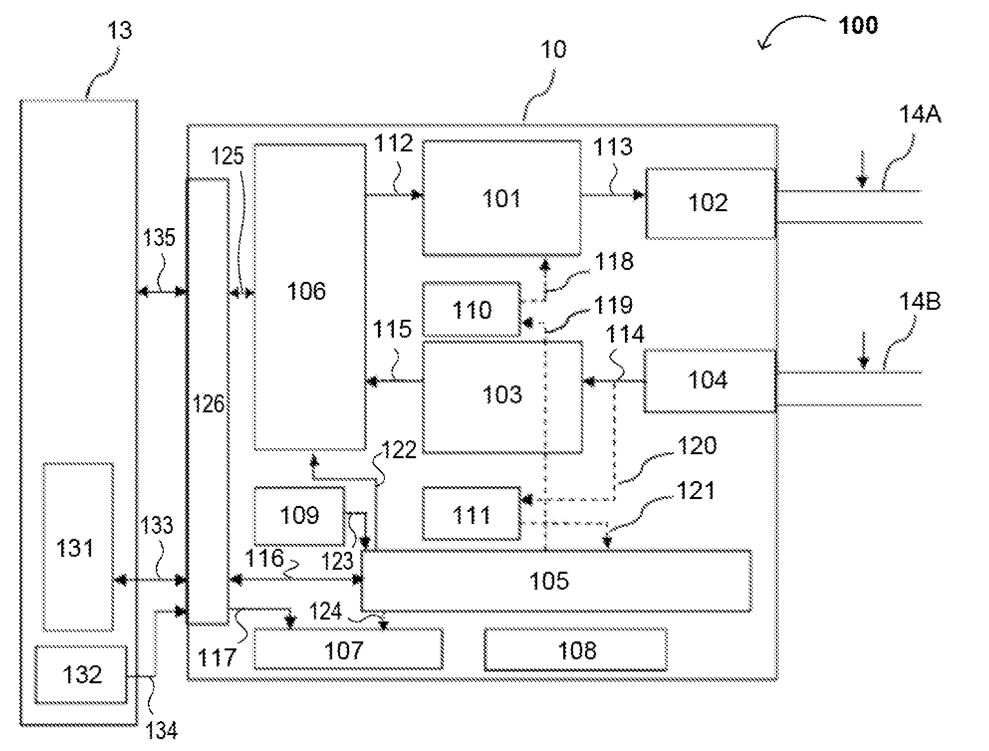
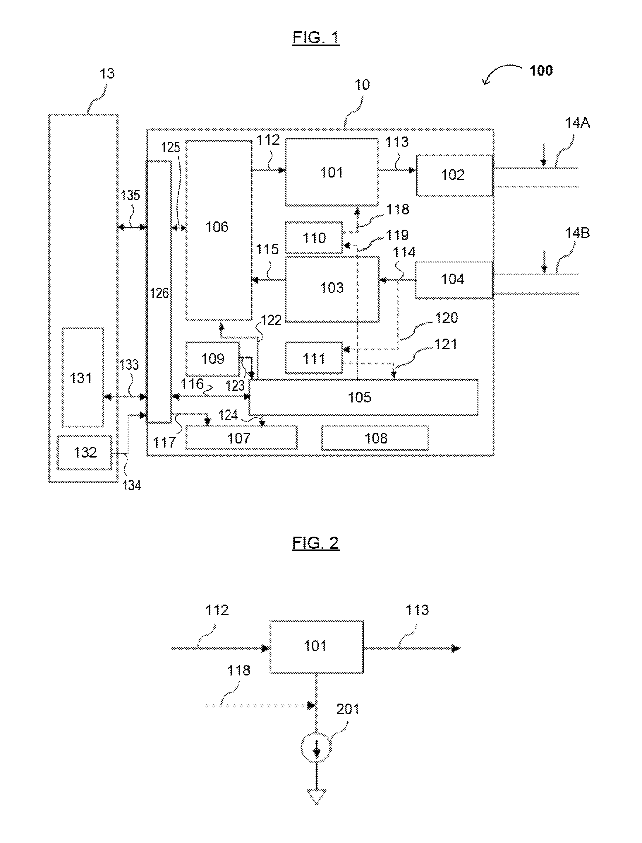
[0034]Reference will now be made in detail to various embodiments, examples of which are illustrated in the accompanying drawings. While the invention will be described in conjunction with the embodiments provided below, the embodiments are not intended to limit the invention. On the contrary, the invention is intended to cover alternatives, modifications and equivalents that may be included within the scope of the appended claims. Furthermore, in the following detailed description, numerous specific details are set forth in order to provide a thorough understanding of the present disclosure. However, the present invention may be practiced without these specific details. In other instances, well-known methods, procedures, components, and circuits have not been described in detail so as not to unnecessarily obscure aspects of the present disclosure.

[0035]Some portions of the detailed descriptions which follow are presented in terms of processes, procedures, logic blocks, functional b...


PUM


Abstract

An optical and/or optoelectrical transceiver and system are disclosed that enable parallel transmission of data and management signals via an optical fiber without affecting data signal transmissions transmitted on the optical fiber. Furthermore, the present transceiver and system provide a fault diagnosis function for an optical fiber link. The transceiver and system generally comprise an interface, an intersecting transmission management unit, a driver, a management signal driving unit, an optical transmitter, an optical receiver, an amplifier, a management signal recovery unit, a management unit, and optionally, a power supply unit.

Description

RELATED APPLICATIONS[0001]This application claims the benefit of Chinese Patent Application Nos. 201020689877.3 and 201010614180.4, both filed on Dec. 30, 2010, each of which is incorporated herein by reference as if fully set forth herein.FIELD OF THE INVENTION[0002]The present invention generally relates to the field of optical and / or optoelectrical communications. More specifically, embodiments of the present invention pertain to circuits, architectures, systems, and methods for data communications in a network using an optical or optoelectrical transceiver which realizes parallel transmission of data and management signals via optical fibers without affecting data signal transmissions transmitted via the optical fiber. Furthermore, the present invention provides a fault diagnosis function for an optical fiber link.BACKGROUND[0003]With rapid development of information technology, data throughput has increased. As a result, networks tend to include equipment with greater data thro...

Claims


Application Information

Patent Timeline
Patent Type & Authority Applications(United States)
IPC IPC(8): H04B10/00H04B10/08
CPCH04B10/0795
Inventor HUANG, YUANJUNZHOU, JIANHUAXIONG, YAXIZHANG, SHENGZHONG
Owner MAGNOLIA SOURCE CAYMAN
Why Eureka
Try Eureka