
Ball Joint

a ball joint and ball joint technology, applied in the direction of rod connections, couplings, suspensions, etc., can solve the problems of high manufacturing cost, high manufacturing cost, and high technology subject, and achieve the effects of low manufacturing cost, high operational reliability, and reduced assembly tim

Active Publication Date: 2012-07-05
THK RHYTHM AUTOMOTIVE GMBH
View PDF17 Cites 18 Cited by
  • Summary
  • Abstract
  • Description
  • Claims
  • Application Information

AI Technical Summary

Benefits of technology

[0015]It is a feature of the invention to provide a ball joint which can be manufactured at low cost while the assembly time is reduced, and which ensures a high operational reliability.

Problems solved by technology

However, this technology is subject to the disadvantage that a machining of the housings is required.
This combination is disadvantageous because of the comparatively high manufacturing costs.
The connection of the sealing bellows shown in FIG. 26 involves additional costs because of the necessary clamping ring and its installation.
But here no interlocking or force-fitting connection is provided between the sealing bellows and the joint socket, so that a preassembly of the sealing bellows and the joint socket is not possible.
A disadvantage here is that costs are incurred for the clamping ring and also its installation.
Such systems, however, are subject to the disadvantages that in the case of a strong press fit, they may lead to the bellows being twisted upon rotation and to a subsequent bellows destruction or, in the case of a press fit of lower strength, they result in an inadequate sealing performance.
Conventional steel designs (FIG. 37) for the above-mentioned strut body are cost-intensive and consist of a solid bar material having a circular cross-section and a joint housing welded thereto.
Further disadvantages of such steel struts are a limited shape forming and a relatively high weight.
Of a disadvantage are a distinctly higher installation space requirement (diameter of the cross-sectional profile), lower structural rigidity, and a strong influence on the structural strength by high or low temperatures.
Further known are strut bodies made of aluminum, which have production limitations and options comparable to those of the plastic material struts.

Method used


Image

  • Ball Joint
  • Ball Joint
  • Ball Joint

Examples


Embodiment Construction

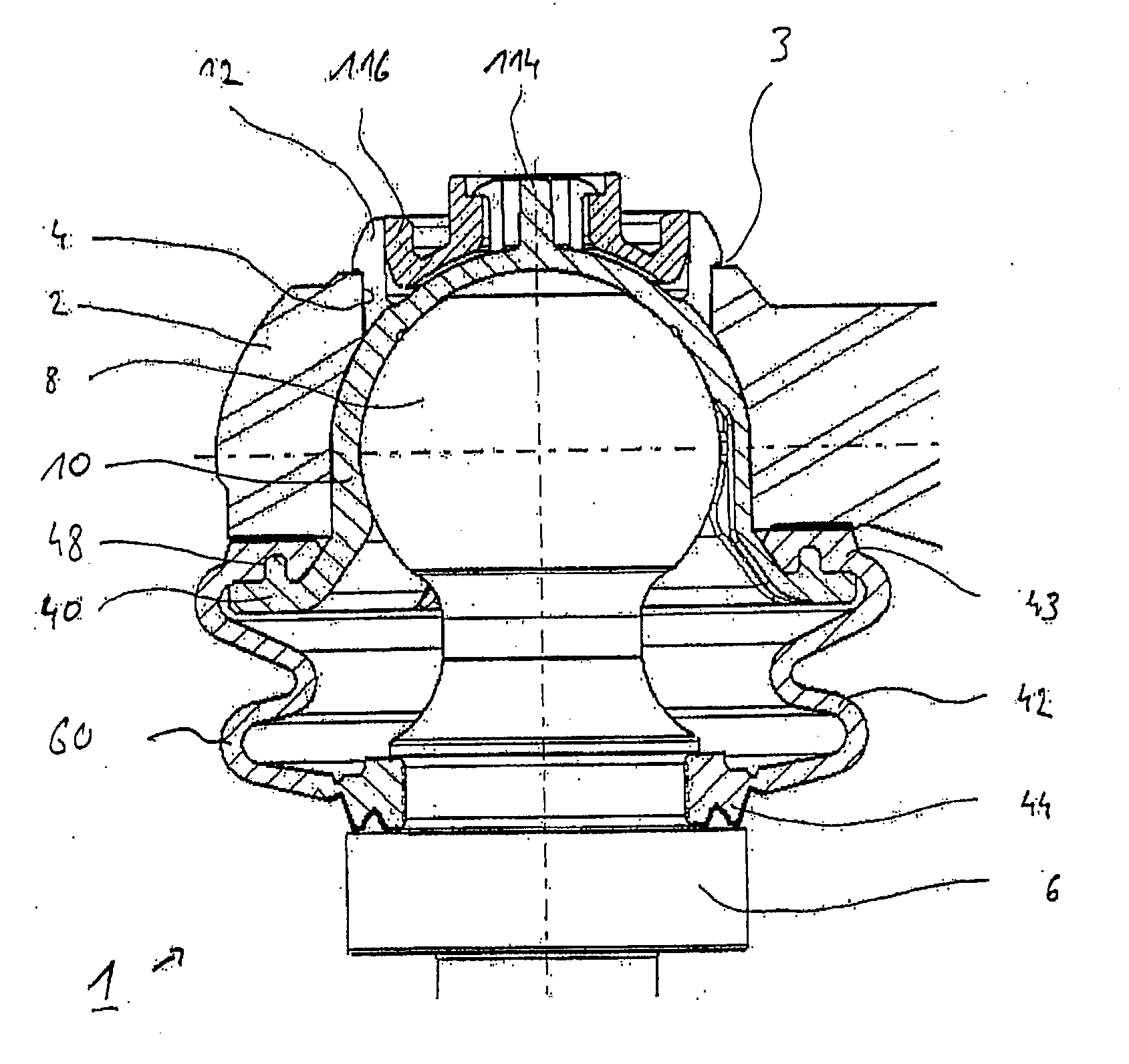
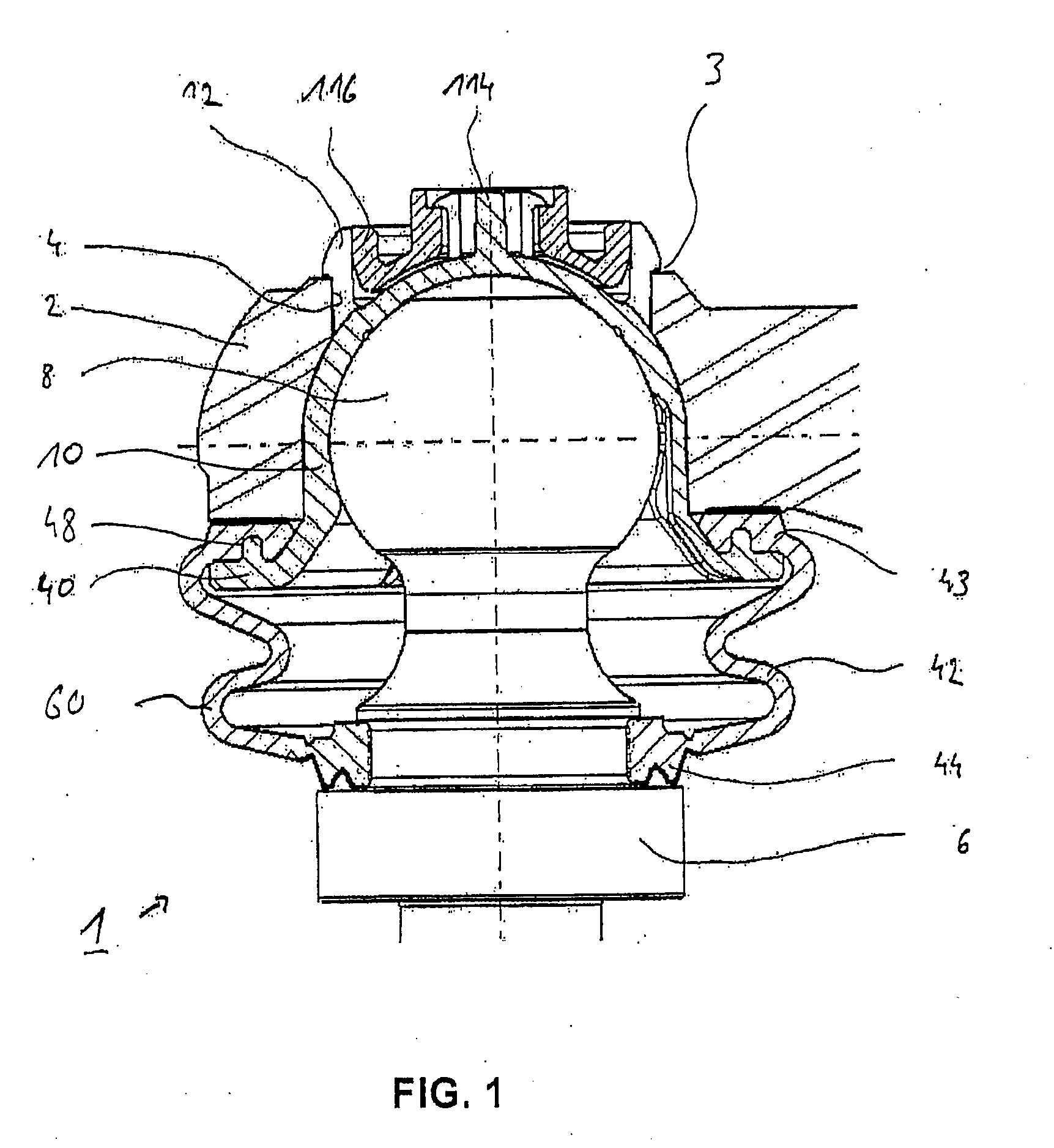
[0092]FIG. 1 shows a ball joint 1 according to the invention, in a fully assembled condition; its essential functional elements will be named and discussed in detail below.

[0093]The ball joint 1 comprises a housing 2 which includes a recess 4 in the form of a passage opening A ball head 8 of a ball stud 6 is locked in the recess 4 of the joint housing 2 by means of a joint socket 10. A captive positioning of the joint socket 10 within the recess 4 is ensured by suitable snap hooks 12 which are locked with a rim 3 of the recess 4.

[0094]For sealing the ball joint 1, provision is made for a sealing bellows 42 which suitably prevents the ingress of dirt or moisture into the interior of the ball joint 1. Similarly, the sealing bellows 42 excludes the leakage of lubricating grease or the like from the interior of the ball joint 1. The sealing bellows 42 is connected or linked to a holding flange 40 of the joint socket 10 by means of a recess 48 in the form of a groove formed on its upper ...


PUM


Abstract

The invention relates to a ball joint, including a joint housing having a recess, a ball stud having a ball head, a sealing bellows having a sealing seat on the housing side and a sealing seat on the stud side in the form of a bellows mouth which is adapted to be brought into contact with the ball stud, a bellows body of the sealing bellows extending between the sealing seat on the housing side and the bellows mouth, and further including a joint socket, the ball head being accommodated for swiveling motion within the joint socket, and the joint socket being inserted in the recess of the joint housing.

Description

CROSS-REFERENCE TO RELATED APPLICATIONS[0001]This application is a national stage of International Application No. PCT / DE2010 / 000725 filed Jun. 24, 2010, the disclosures of which are incorporated herein by reference, and which claimed priority to German Patent Application No. 10 2009 031 738.4 filed Jun. 30, 2009, German Patent Application No. 10 2009 031 289.7 filed Jun. 30, 2009, German Patent Application No. 10 2009 031 290.0 filed Jun. 30, 2009, German Patent Application No. 10 2009 031 283.8 filed Jun. 30, 2009, and German Patent Application No. 10 2009 031 284.6 filed Jun. 30, 2009, the disclosures of which are incorporated herein by reference in their entirety.BACKGROUND OF THE INVENTION[0002]The present invention relates to a ball joint which is in particular suitable for use in the chassis area of a motor vehicle.[0003]Numerous ball joints for motor vehicles are known from the prior art. Such ball joints typically consist of a ball stud which is movably supported in a joint...

Claims


Application Information

Patent Timeline
IPC IPC(8): F16C11/06F16J15/52
CPCY10T403/32729F16J3/042Y10T403/32737F16C11/0671F16C11/0657F16C2226/74Y10T403/31Y10T403/32631F16C11/069F16C11/0642F16C11/0638F16C7/02B60G2204/416B60G2204/42B60G2204/4404F16C2326/05
Inventor FORTHAUS, UWEPAUL, ALEXANDERMETTE, ULRICHWALTER, HARALD
Owner THK RHYTHM AUTOMOTIVE GMBH
Learn More