Amplifier with On-Chip Filter

a technology of filter and amplifier, applied in the direction of electrical equipment, transmission, network with variable switch closing time, etc., can solve the problems of increasing the cost and complexity of baluns, increasing the cost of radio receivers, and the inability of pre-selection filters to be integrated on silicon

Active Publication Date: 2012-07-05
TELEFON AB LM ERICSSON (PUBL)
View PDF10 Cites 5 Cited by
  • Summary
  • Abstract
  • Description
  • Claims
  • Application Information

AI Technical Summary

Problems solved by technology

With current technologies, pre-selection filter can not be integrated on silicon, because the required quality (Q) factors in the filter can not be realized.
In present technologies, since the center frequencies of the SAW / BAW filters are fixed, several pre-selection filters are needed in radio receivers for multi-standard or multi-mode applications, increasing the cost and complexity.
In multi-mode radio receivers, multiple RF pre-selection filters, switches, and baluns increase significantly the cost of the radio receiver.
In addition, this decreases the integration level of the receiver, and increase the bills-of-material (BOM) and complexity of the printed circuit board (PCB).
The cost of the actual RXIC is also increased due to the fact that several RF input pins, which are also usually balanced, are needed.
In other words, due to the nonlinearity in the radio receiver, a large blocking signal can desensitize the receiver or reduce the gain of the small desired signal.

Method used


Image

  • Amplifier with On-Chip Filter
  • Amplifier with On-Chip Filter
  • Amplifier with On-Chip Filter

Examples


Embodiment Construction

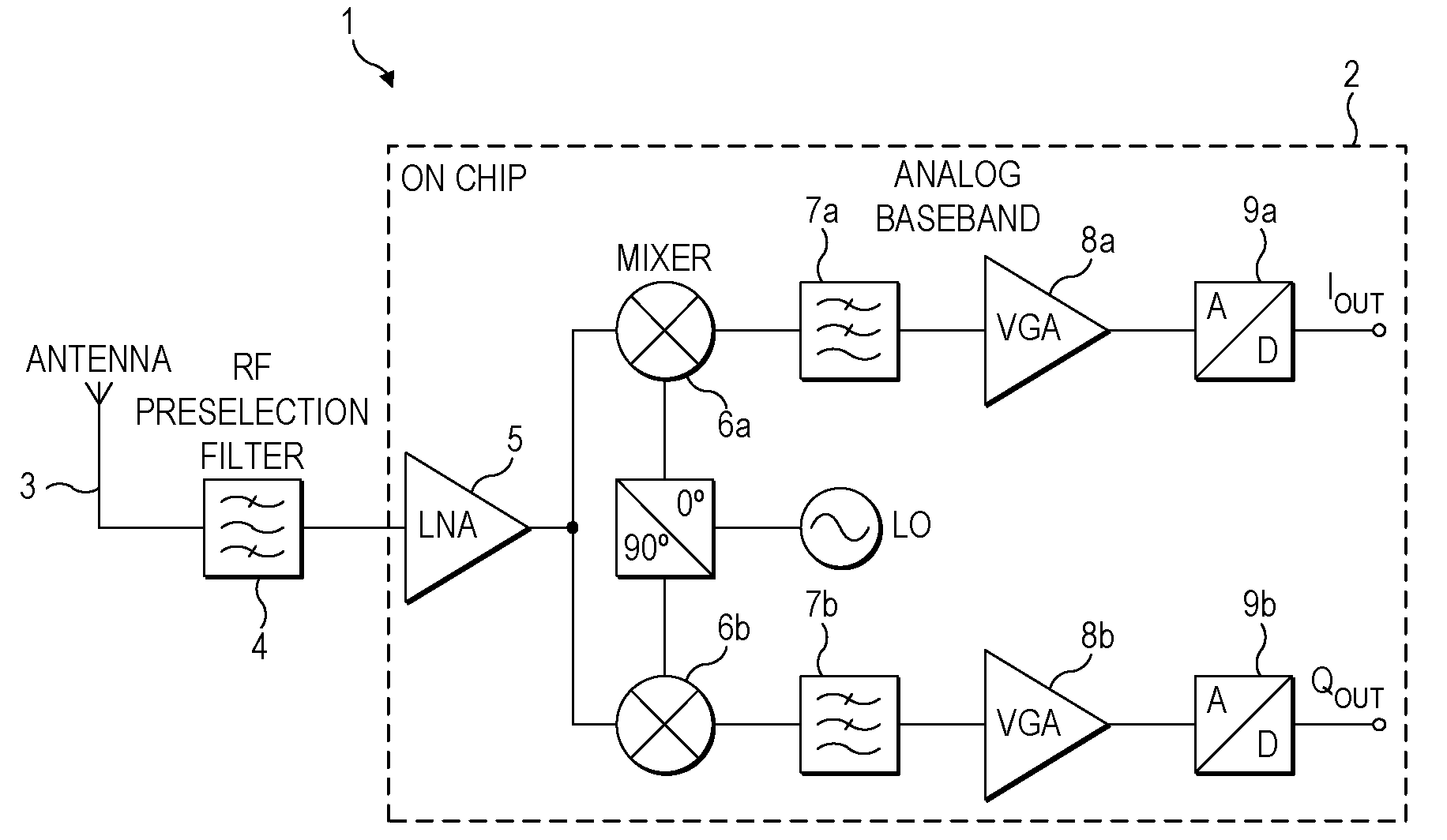
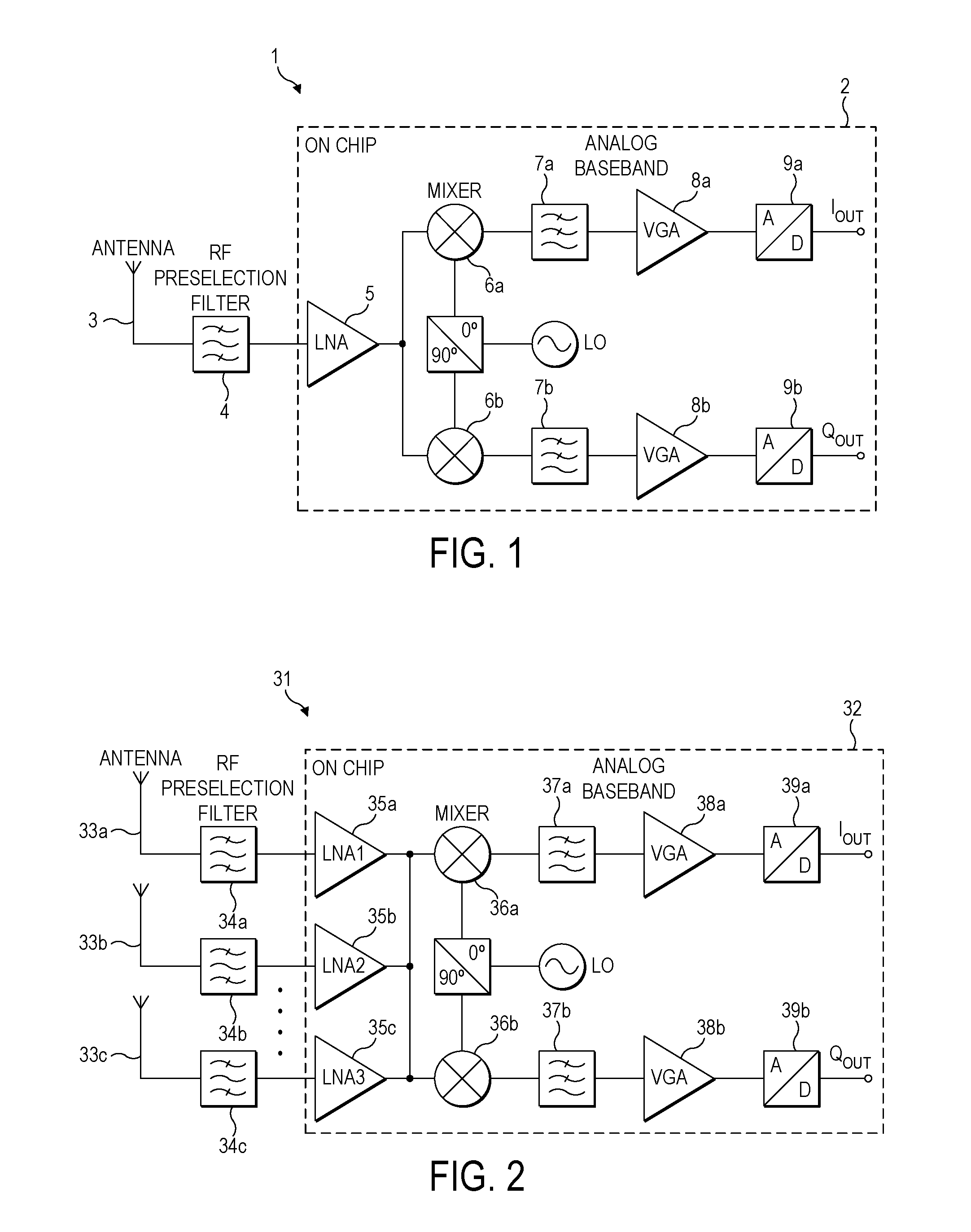
[0028]FIG. 1 is a block diagram of a single-band zero-IF receiver architecture. In the receiver 1 illustrated in FIG. 1, the antenna 3 feeds the received RF signal to an RF band-pass filter 4 (pre-selection filter) that performs the pre-selection of the received RF band. The LNA 5, which is usually the first integrated block of the receiver IC 2, amplifies the RF signal in order to reduce the noise contributions of the following stages. I and Q down-conversion mixers 6a, 6b convert the signal to analog baseband. The down-converted signals are filtered by respective low-pass filters 7a, 7b output to respective variable gain stages 8a, 8b. Finally, respective analog-to-digital converters (ADC) 9a, 9b convert the analog signal from the respective gain stages 8a, 8b to a digital form.

[0029]FIG. 2 is a block diagram of a zero-IF receiver architecture for a multi-mode or multi-standard application requiring several external RF filters. In the receiver 31 illustrated in FIG. 2, three anten...


PUM


Abstract

An integrated circuit for a radio receiver comprising a radio-frequency amplifier and a radio-frequency filter is described. The amplifier receives radio-frequency signals from an antenna, the filter is connected to the amplifier output, and the output of the filter is provided to a processing stage of the receiver. The amplifier comprises an amplifying stage controlled by a radio-frequency input signal and a signal fed back from the filter. The amplifier input impedance is substantially matched to the antenna impedance at a frequency band of interest. The signal fed back from the filter providing attenuation of signals outside the frequency band of interest at the amplifier input. The filter comprises one or more filter components. A filter component comprises a first input and a second input for receiving the amplifier output, a first switch arranged to selectively connect the first input to a first impedance, a second switch arranged to selectively connect the first input to a second impedance, a third switch arranged to selectively connect the second input to the first impedance, and a fourth switch arranged to selectively connect the second input to the second impedance. The first and fourth switches are controlled by a first oscillator signal and the second and third switches are controlled by a second oscillator signal that is 180° out of phase with the first oscillator signal.

Description

[0001]The present invention relates to integrated circuits for radio receivers.BACKGROUND OF THE INVENTION[0002]In a typical wireless radio receiver, an external radio frequency (RF) pre-selection filter is used at the front of the actual integrated radio receiver circuit (RXIC) to filter out harmful out-of-band blocking signals and to alleviate the linearity requirements of the RXIC. With current technologies, pre-selection filter can not be integrated on silicon, because the required quality (Q) factors in the filter can not be realized. In most cases, RF filters are realized either with surface or bulk acoustic wave techniques (SAW / BAW). In present technologies, since the center frequencies of the SAW / BAW filters are fixed, several pre-selection filters are needed in radio receivers for multi-standard or multi-mode applications, increasing the cost and complexity.[0003]One known amplifier design is described in P. Rossi et al, “A Variable Gain RF Front-End, Based on Voltage-Volta...

Claims


Application Information

Patent Timeline
Patent Type & Authority Applications(United States)
IPC IPC(8): H04B1/18
CPCH03H19/008
Inventor SIVONEN, PETERIEKKI, JONNEKAUKOVUORI, JOUNIVILHONEN, SAMIJUSSILA, JARKKO
Owner TELEFON AB LM ERICSSON (PUBL)
Why Eureka
Try Eureka