Liquid Cooling System Cold Plate Assembly

a technology of liquid cooling system and cold plate, which is applied in the direction of stationary conduit assembly, lighting and heating apparatus, laminated elements, etc., can solve the problems of degrading system performance, localized heat sources or hot spots within the chassis environment, and motherboard and various auxiliary components consuming power and generating heat, etc., to facilitate efficient thermal energy transfer

Inactive Publication Date: 2012-07-12
ASETEK DANMARK
View PDF2 Cites 98 Cited by
  • Summary
  • Abstract
  • Description
  • Claims
  • Application Information

AI Technical Summary

Benefits of technology

[0013]In an alternate embodiment of the present disclosure, a flow of liquid coolant entering the enclosing housing is directed towards the surface of the base component by inlet baffles which define a channel or groove. The directed flow of liquid coolant facilitates efficient transfer of thermal energy from the high thermal-conductivity insert to the base component, and into the flow of liquid coolant for transport away.

Problems solved by technology

During operation, the motherboard and various auxiliary components consume power and generate heat.
Individual integrated circuits, especially memory modules and processors, may generate significant amounts of heat during operation, resulting in localized heat sources or hot spots within the chassis environment.
Failure to maintain adequate temperature control throughout the chassis environment, and at individual integrated circuits, can significantly degrade the system performance and may eventually lead to component failure.
However, as personal computer systems include increasing numbers of individual components and integrated circuits, and applications become more demanding on additional processing components such as graphics display adapters, a system power supply cooling fan may be inadequate to maintain the necessary operating temperatures within the chassis environment.
Being composed of metal, the cold plate is generally an expensive and heavy component in any liquid cooling system.
For some metals, which are ideal heat transfer pathways, the formation of the protrusions, fins, or foils is difficult or time consuming.
For example, to form a cold plate from copper, with the necessary protrusions to the required tolerances, a complex sintering process is required which is time consuming and expensive.
With other types of metals, such as aluminum, the necessary protrusions may be readily formed at a reduced cost by a direct molding process, but lack the heat transfer characteristics of copper.
If the two different types of metals are utilized in combination, it is possible that a galvanic corrosion may occur if each metal is in contact with the liquid coolant, leading to a failure of the liquid cooling system, either through corrosion buildup or leakage of the liquid coolant.
Specialized liquid cooling systems can additionally suffer from regions of low fluid flow within the fluid chambers coupled to the cold plates, leading to inefficient operations, such as shown in FIG. 4.
This can be caused by dispersal of the inflow of liquid coolant within the chamber as it enters the chamber, leading to the formation of “dead zones” within the chamber wherein a flow of the liquid coolant is minimal.

Method used


Image

  • Liquid Cooling System Cold Plate Assembly
  • Liquid Cooling System Cold Plate Assembly
  • Liquid Cooling System Cold Plate Assembly

Examples


Embodiment Construction

[0023]The following detailed description illustrates the invention by way of example and not by way of limitation. The description enables one skilled in the art to make and use the present disclosure, and describes several embodiments, adaptations, variations, alternatives, and uses of the present disclosure, including what is presently believed to be the best mode of carrying out the present disclosure.

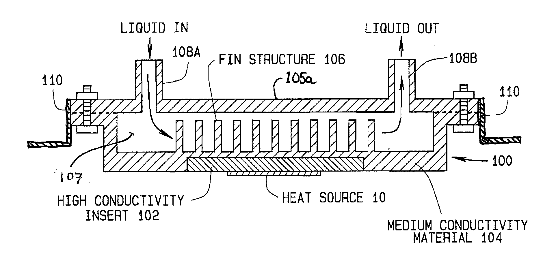
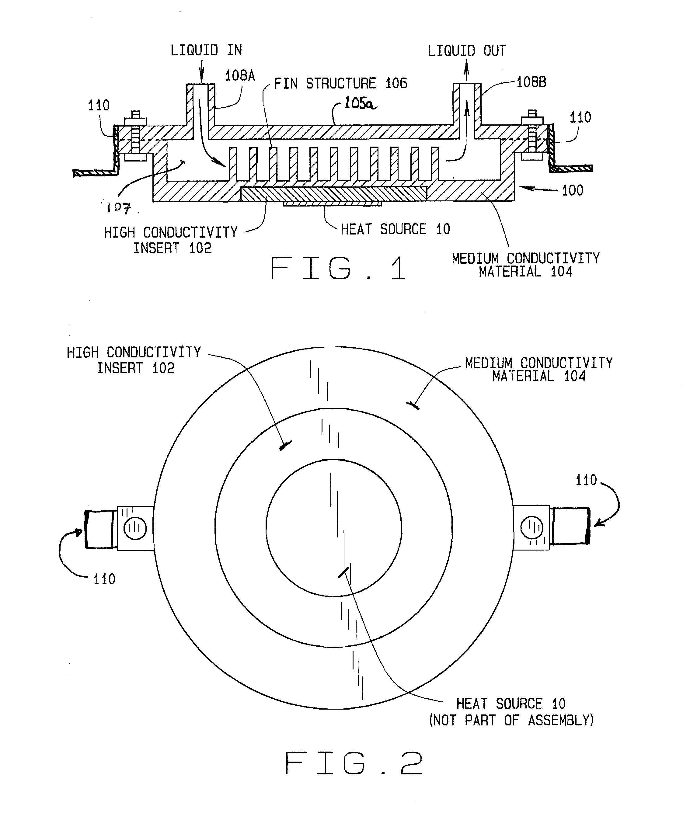
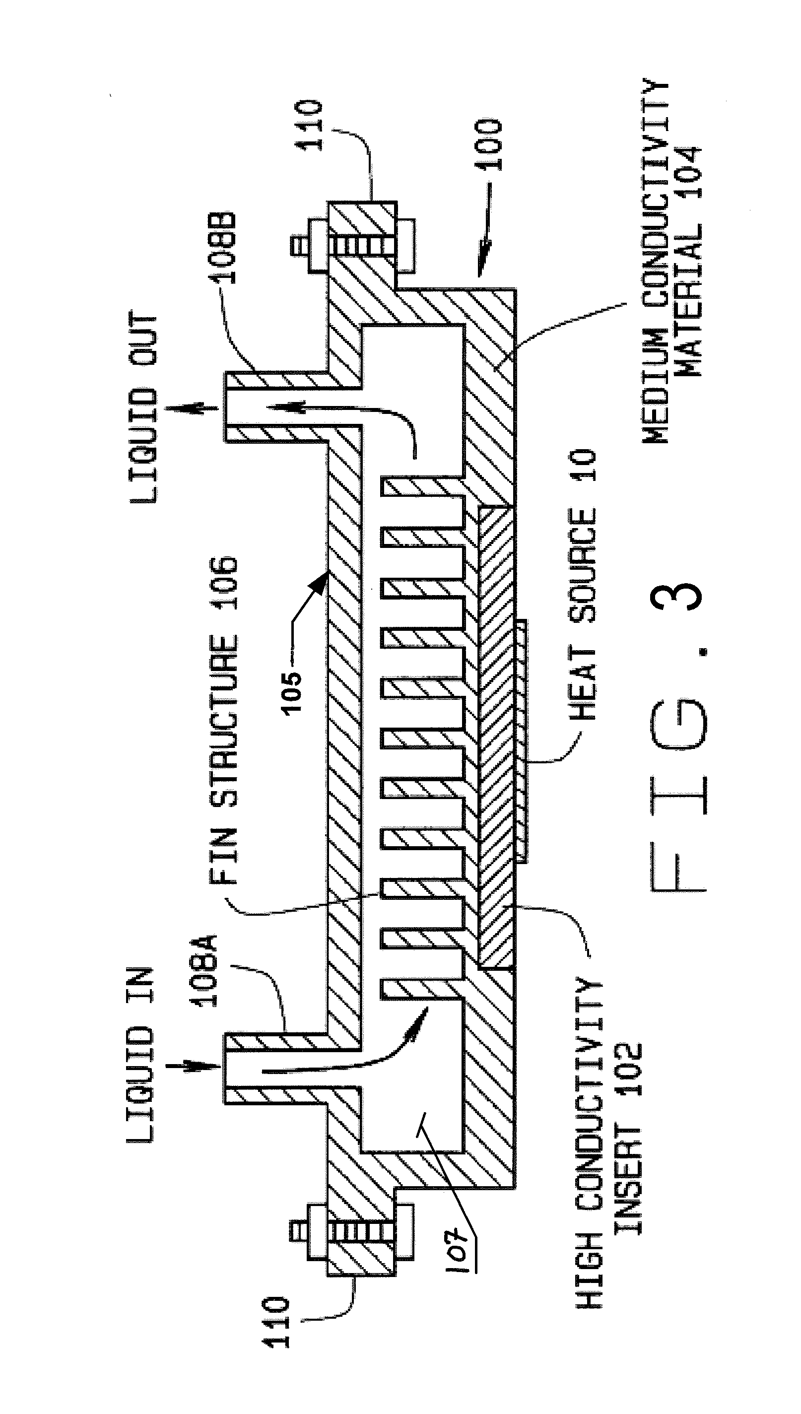
[0024]Turning to the Figures, a cold plate assembly 100 of the present invention adapted for secured over a heat source 10 such as an integrated circuit, video or graphic processing unit is shown configured for connection to an existing liquid cooling circulating flow loop via any suitable liquid pathway. The liquid cooling loop, which is not directly part of the present invention, provides all necessary components for circulating a flow of liquid coolant to and from the cold plate assembly 100 through inlets 108A and outlets 108B, thereby drawing heat away from the various heat-gen...


PUM


Abstract

A cold plate assembly consisting of a thermally conductive base component with an insert having a high thermal transfer characteristic adapted for contacting the surface of a heat source on one side. The surface of the base component opposite from the insert is surrounding by a housing defining an enclosed volume through with a flow of liquid coolant is directed. Inlet baffles adjacent to a fluid inlet in the housing direct the incoming flow of liquid coolant towards the surface of the base component in proximity to the insert, facilitating an efficient transfer of thermal energy from the heat source to the liquid coolant through the insert and base component. Optional extensions or fins extending into the liquid coolant contained in the enclosed volume from the surface of the base component further facilitate the transfer of thermal energy from the heat source.

Description

CROSS-REFERENCE TO RELATED APPLICATIONS[0001]None.STATEMENT REGARDING FEDERALLY SPONSORED RESEARCH[0002]Not Applicable.BACKGROUND OF THE INVENTION[0003]The present invention is related generally to liquid cooling systems adapted for use in cooling heat sources such as integrated circuit components, processors, and memory modules in a computer system, and in particular to a cold plate assembly configured for facilitating efficient heat exchange between the heat source and a directed flow of cooling liquid circulated through a chamber within the assembly.[0004]Personal computer systems which are design for desktop or under-desk use, and which are typically characterized by a main-board or motherboard housed in a chassis or case, often provide one or more expansion slots into which auxiliary components may be installed. These auxiliary components may include network adapter circuit boards, modems, specialized adapters, and graphics display adapters. These auxiliary components may recei...

Claims


Application Information

Patent Timeline
Patent Type & Authority Applications(United States)
IPC IPC(8): F28F3/12
CPCF28D1/03F28F3/048F28F3/12H01L23/3672H01L2924/0002H01L23/473H01L2924/00
Inventor RICE, JEREMY A.
Owner ASETEK DANMARK
Why Eureka
Try Eureka