System for decoupling a rotor from a stator of a permanent magnet motor and flywheel storage system using the same

a technology of permanent magnet motor and storage system, which is applied in the direction of wind energy generation, magnetic circuit, dynamo-electric motor/converter starter, etc., can solve the problems of not being able to achieve a wide range of applications, not being able to meet the requirements of high-power supply, and aerodynamic losses essentially losses, etc., to achieve the effect of high efficiency

Inactive Publication Date: 2012-07-12
UNIV LAVAL
View PDF0 Cites 16 Cited by
  • Summary
  • Abstract
  • Description
  • Claims
  • Application Information

AI Technical Summary

Benefits of technology

[0020]The system for decoupling a rotor from a stator of a permanent magnet motor enables to increase the range of speed of the motor that admits constant power, which is of great advantage.
[0021]The system for decoupling a rotor from a stator of a permanent magnet motor enables to totally decouple the rotor from the stator of the motor to cancel the magnetic losses during a conservative mode, which is of great advantage.
[0025]In another embodiment, the displacement mechanism enables a continuous motion of the selected one of the stator and the rotor between the first position and the second position.
[0026]In a further embodiment, the stator and the rotor have no magnetic interaction when extending in the second position, to thereby reduce magnetic losses in the permanent magnet motor.
[0049]The flywheel energy storage system may provide high efficiency energy storage, particularly for long term energy storage applications, which is of great advantage.

Problems solved by technology

They are generally known to supply high power during a short period of time, but are also known to be not well suited for supplying high power over a long period of time, as it will become apparent below.
Finally, aerodynamic losses are essentially the losses due to the friction of the rotating parts of the flywheel with the air in the containment vessel.
Minimizing those losses is not easy to achieve because they are all interrelated.
For instance, the reduction of friction losses can be achieved with magnetic bearings instead of mechanical bearings, but that particular embodiment will increase the magnetic and electric losses of the whole system.
They are however also known for their iron losses at no load and their short range of speed at a constant power, two major drawbacks for the flywheel energy storage systems of the art.
This particular method requires the oversizing of the supplying inverter and increases the losses of the inverter and of the motor-generator.

Method used


Image

  • System for decoupling a rotor from a stator of a permanent magnet motor and flywheel storage system using the same
  • System for decoupling a rotor from a stator of a permanent magnet motor and flywheel storage system using the same
  • System for decoupling a rotor from a stator of a permanent magnet motor and flywheel storage system using the same

Examples


Embodiment Construction

[0065]In the following description of the embodiments, references to the accompanying drawings are by way of illustration of examples by which the invention may be practiced. It will be understood that other embodiments may be made without departing from the scope of the invention disclosed.

[0066]As known to the skilled addressee, the range of rotational speed in which a permanent magnet motor is able to provide a constant power is very limited, which is a great drawback for various given applications.

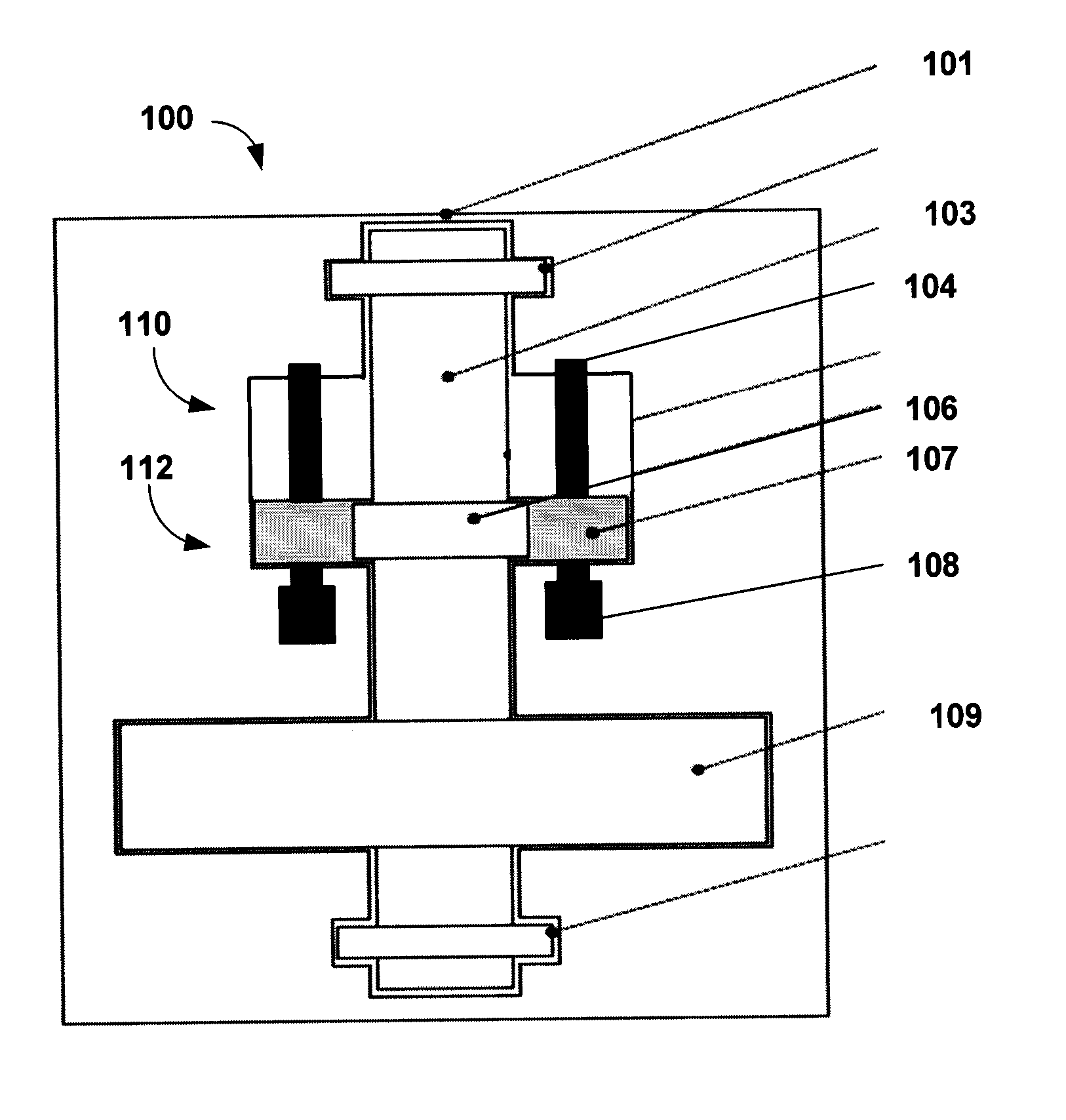
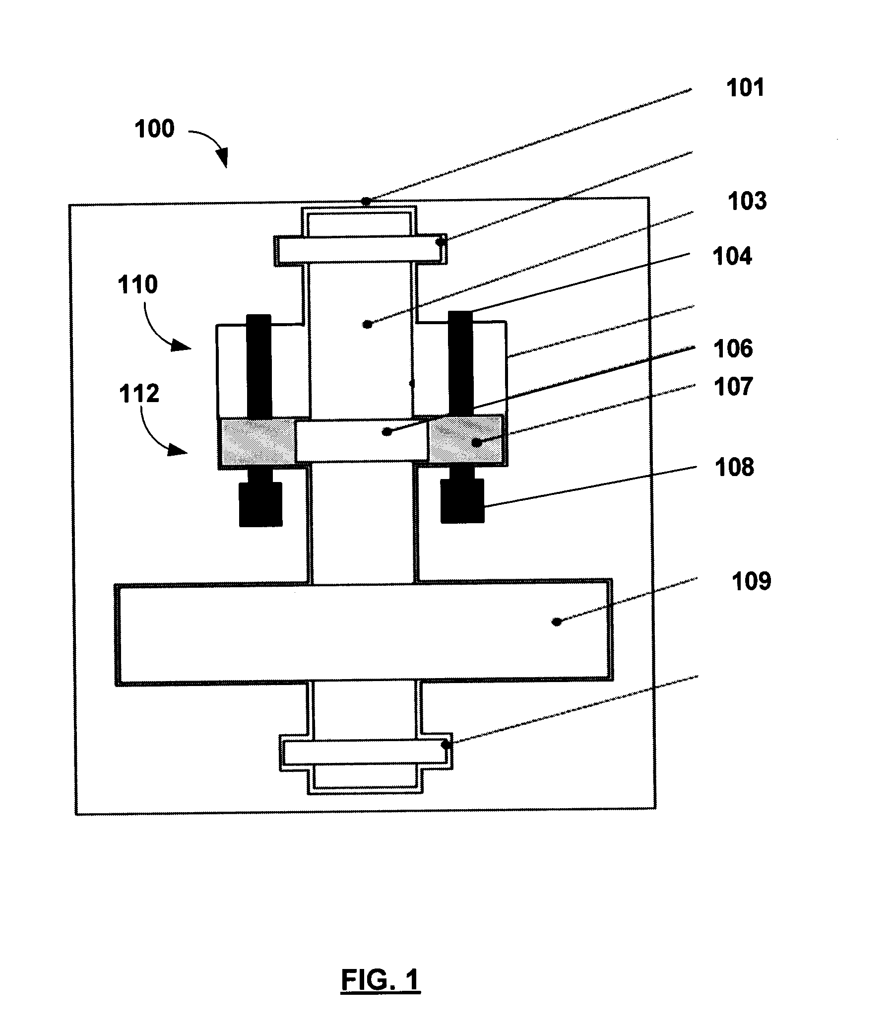
[0067]As it will become apparent upon reading of the present description, the system for decoupling a rotor from a stator of a permanent magnet motor, hereinafter also referred to as the decoupling system or the magnetic active coupler, enables the increasing of the range of speed on which constant power may be provided, which is of great advantage.

[0068]The system also enables a conservative mode where the stator is totally decoupled from the rotor, which is of great advantage since i...


PUM


Abstract

A system for decoupling a rotor from a stator of a permanent magnet motor and a flywheel storage system using the same are provided. The flywheel storage system uses the permanent magnet motor as a magnetic active coupler to minimize magnetic losses in flywheel energy storage system during the motor-generator electric power transfer for enabling a magnetic field weakening method and a way of cancelling the losses during a conservative mode where the stator is totally decoupled from the rotor. Also, the present invention enables the optimal sizing of a permanent motor-generator to be able to supply a constant power over a large range of rotating speeds.

Description

CROSS REFERENCE TO RELATED APPLICATIONS[0001]This application claims priority of U.S. Patent Application having Ser. No. 61 / 187,174 which was filed on Jun. 15, 2009 and entitled “SYSTEM FOR DECOUPLING A ROTOR FROM A STATOR OF A PERMANENT MAGNET MOTOR AND A FLYWHEEL STORAGE SYSTEM USING THE SAME”, the specification of which is hereby incorporated by reference.[0002]This application also claims priority of U.S. Patent Application having Ser. No. 61 / 233,664 which was filed on Aug. 13, 2009 and entitled “ENERGY STORAGE SYSTEM AND METHOD”, the specification of which is hereby incorporated by reference.[0003]The present application also relates to PCT Application entitled “ENERGY STORAGE SYSTEM AND METHOD” filed on Jun. 15, 2010 by the same Applicant, the specification of which is incorporated herein by reference.FIELD OF THE INVENTION[0004]The invention relates to high energy flywheel storage systems using permanent magnet motor for long term energy storage. More particularly, the invent...

Claims


Application Information

Patent Timeline
Patent Type & Authority Applications(United States)
IPC IPC(8): H02P23/00
CPCB60K6/105Y10T74/2119H02J9/066H02J15/00H02K7/025Y02E10/725Y02E60/16Y02E70/30Y02T10/6204Y02T10/6269Y02T10/90H02J3/381H02J3/383H02J3/386Y02E10/563Y02E10/763H02J3/382H02M7/5388Y04S10/126Y02E60/721Y02T10/6282Y10T74/212F16F15/305H02J2300/40H02J2310/48H02J2300/28H02J2300/20H02J2300/24Y02B10/70Y02E10/56Y02E10/76Y02E10/72Y02T10/62H02J15/007Y02E60/00
Inventor DUBOIS, MAXIME R.DESJARDINS, MICHAELTREMBLAY, LOUIS
Owner UNIV LAVAL
Why Eureka
Try Eureka