Optical connector with lenses having opposing angled planar surfaces

a technology of optical connectors and planar surfaces, applied in the field of optical connectors, can solve the problems of connectors not substantially reducing the performance of optical connectors, not suitable for consumer electronic devices, and not intended for the relatively large number of mating cycles normally associated with consumer electronic devices

Inactive Publication Date: 2012-07-12
CORNING INC
View PDF6 Cites 47 Cited by
  • Summary
  • Abstract
  • Description
  • Claims
  • Application Information

AI Technical Summary

Problems solved by technology

Generally speaking, conventional optical connectors used for telecommunication networks and the like are not suitable for consumer electronic devices.
Further, though optical connectors used in telecommunications are reconfigurable (i.e., suitable for mating / unmating), they are not intended for the relatively large number of mating cycles normally associated with consumer electronic devices.
Consequently, an optical connector used for commercial electronic devices must be designed so that any contaminants (e.g., dust, dirt, debris, fluid, etc.) that find their way into the optical connector do not substantially reduce optical connector performance.
However, such anti-reflective coatings increase the complexity and cost of the optical connector.
However, the use of index-matching fluids is not practical in applications where a connector needs to be routinely disconnected and connected where the optical surfaces are interfaced.
Moreover, certain consumer electronic devices have size and space constraints for making connections and may not be amenable to a straight optical connection, so that an optical connector with a bend is also desirable.

Method used


Image

  • Optical connector with lenses having opposing angled planar surfaces
  • Optical connector with lenses having opposing angled planar surfaces
  • Optical connector with lenses having opposing angled planar surfaces

Examples


Embodiment Construction

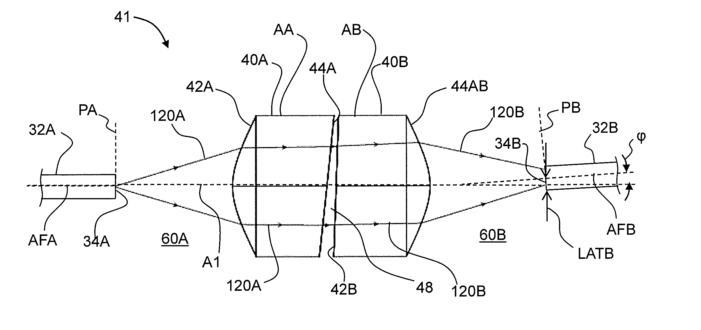
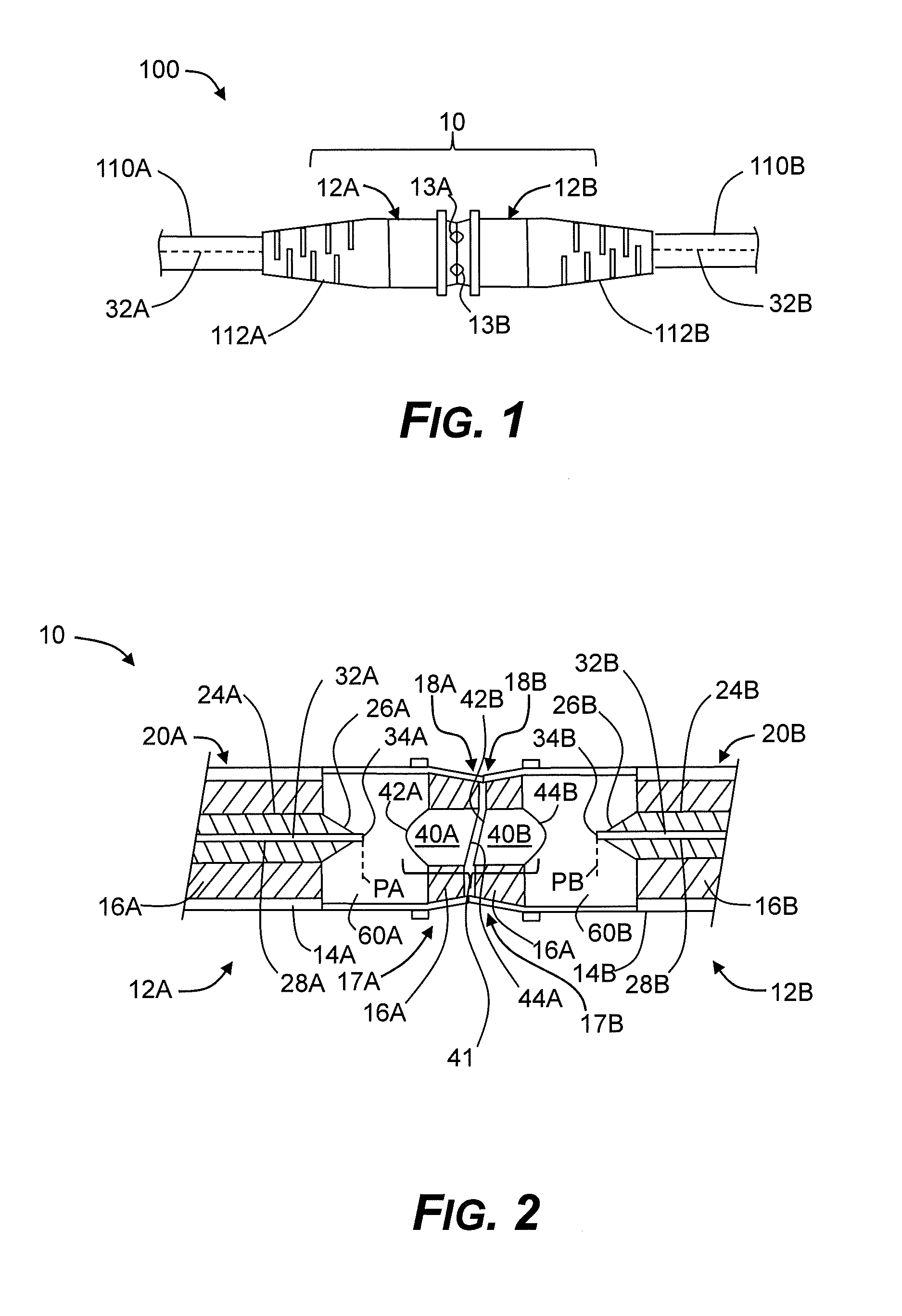
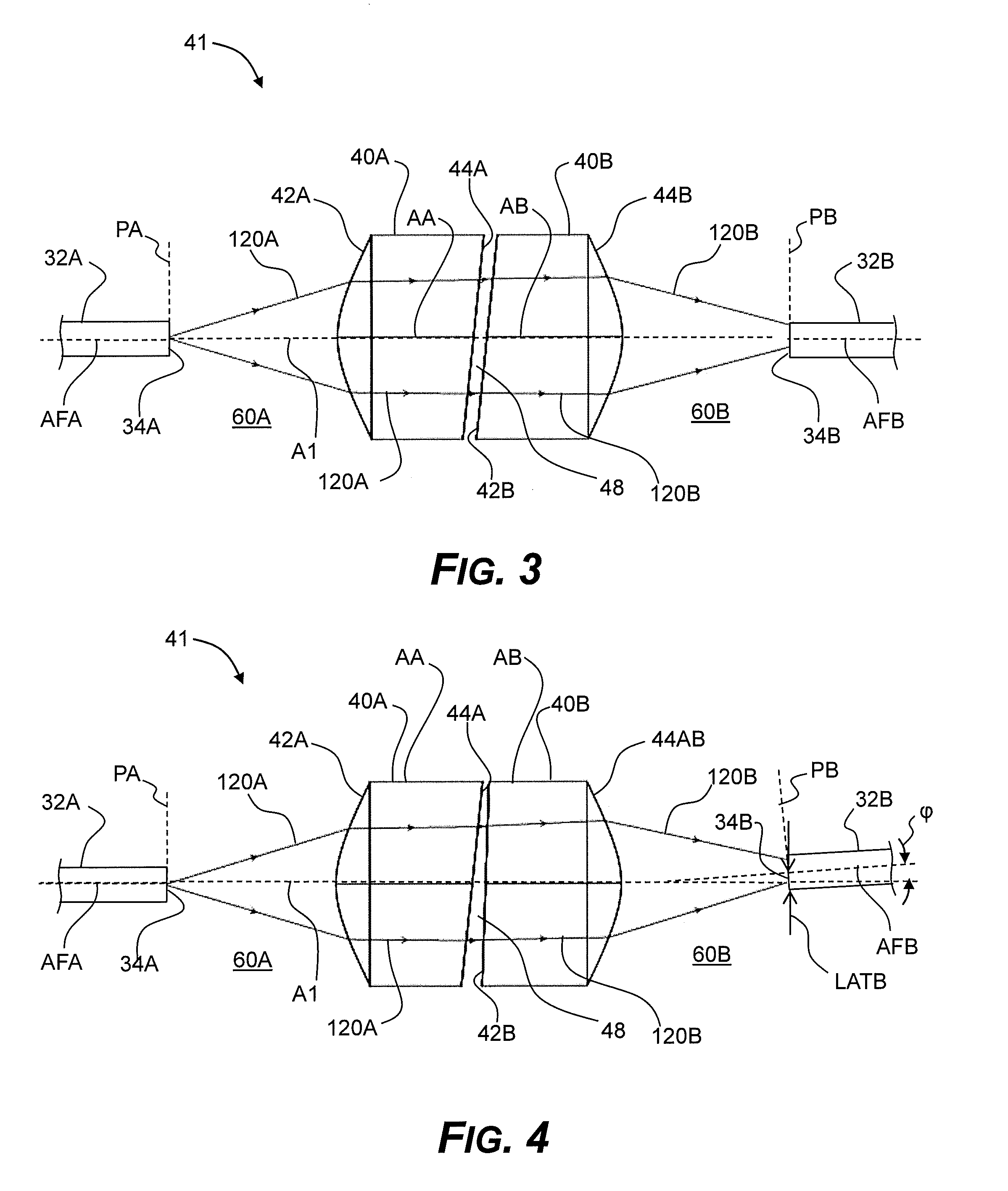
[0032]FIG. 1 is a side view of an example connector assembly 100 that includes an optical connector 10 according to the present disclosure. FIG. 2 is a close-up, longitudinal cross-sectional view of an example optical connector 10 of the connector assembly of FIG. 1. Optical connector 10 includes first and second mating connector members 12A and 12B having a similar (but not necessarily identical) structure. For ease of description, connector member 12A is referred to herein as “plug 12A” and connector member 12B is referred to as “receptacle 12B.” Note that this terminology is a matter of choice and can be reversed. Also, in the Figures, light travels left to right unless indicated otherwise.

[0033]Connector assembly 100 includes plug and receptacle fiber optic cables 110A and 110B that are respectively connected to plug 12A and receptacle 12B of optical connector 10. Plug and receptacle fiber optic cables 110A and 110B respectively carry at least one plug optical fiber 32A and at l...


PUM


Abstract

An optical connector for optically connecting at least one light source to at least one light receiver is disclosed. The optical connector includes first and second connector members respectively having first and second positive-power lens elements with respective first and second planar lens surfaces. The lens elements are arranged in their respective connector members such that when the two connector members are operably mated, the first and second lenses form an optical system where the first and second planar lens surfaces are spaced apart in opposition with a narrow gap in between, and are non-perpendicular to the optical system axis. The lenses may be conventional uniform-refractive-index lenses having a convex surface or may be gradient-index lenses having two planar surfaces. The optical connector is tolerant to contamination that can find its way into the narrow gap.

Description

CROSS-REFERENCE TO RELATED APPLICATIONS[0001]This application claims the benefit of priority under 35 U.S.C. §119 of U.S. Provisional Application Ser. No. 61 / 431,517 filed on Jan. 11, 2011, the content of which is relied upon and incorporated herein by reference in its entirety.FIELD[0002]The disclosure is directed to optical connectors, and in particular relates to optical connectors with lenses having opposing angled planar surfaces.BACKGROUND ART[0003]Optical fiber is increasingly being used for a variety of applications, including but not limited to broadband voice, video, and data transmission. As consumer devices increasingly use more bandwidth, it is anticipated that connectors for these devices will move away from electrical connections and toward using optical connections or a combination of electrical and optical connections to meet the bandwidth needs.[0004]Generally speaking, conventional optical connectors used for telecommunication networks and the like are not suitabl...

Claims


Application Information

Patent Timeline
Patent Type & Authority Applications(United States)
IPC IPC(8): G02B6/38B23P11/00
CPCG02B6/327G02B6/4204Y10T29/49826G02B6/4214G02B6/4207
Inventor DEMERITT, JEFFERY ALANFORTUSINI, DAVIDE DOMENICOSUTHERLAND, JAMES SCOTT
Owner CORNING INC
Why Eureka
Try Eureka