Eureka AIR delivers breakthrough ideas for toughest innovation challenges, trusted by R&D personnel around the world.

Method for diagnosing an exhaust gas post-treatment

Inactive Publication Date: 2012-07-19
FEV
View PDF7 Cites 1 Cited by
  • Summary
  • Abstract
  • Description
  • Claims
  • Application Information

AI Technical Summary

Benefits of technology

[0008]As individual method steps it can be provided, that the exhaust gas component is acquired over a time interval, which extends from a first point in time during the starting phase of the regeneration at least up to a second point in time during the regeneration, preferably, at the end of the regeneration. In this case, it can be provided, that the first point in time coincides with the starting of the regeneration or can be after the start of the regeneration. If the first point in time coincides with the start of the regeneration, this has the advantage of a simple starting condition. Generally, the start of the regeneration is carried out by measures inside the engine like throttling, later injection timing, additional and / or later injection. Intentionally, non-combusted fuel amounts reach the oxidation catalyst. Because of the thus forced reactions in the oxidation catalyst, the exhaust gas temperature increases up to approximately 620° C. to 630° C. inside the same, however, only with some time delay to the start of the measures inside the engine. During this time interval, a breakthrough or a slippage of the exhaust gas component, not converted by the oxidation catalyst, can take place. Only after the oxidation catalyst has been heated up to an exhaust gas temperature of approximately 620° C. to 630° C., this exhaust gas component is converted. This can be designated as the end of the starting phase. The heated exhaust gas starts then the burning-off procedure of the carbon-particulates in the particle filter. To not determine this portion of the non-converted exhaust gas component, the first point in time of the measurement can be later than the starting of the regeneration by means of the sensor means arranged downstream of the particle filter. As a release condition for the temporal determination of this point in time relative to the starting of the regeneration, the temperature of the exhaust gas behind the oxidation catalyst can be used.

Problems solved by technology

Problems arise from the fact, that this catalytic layer ages within the particle filter, so that it becomes inactive and a conversion of the carbon monoxide, produced by the regeneration, is not ensured anymore.
This ageing process of the catalytic coating and the, thus, increased carbon monoxide emission during the regeneration of the particle filter is in practice a not directly recognisable problem.

Method used


Image

  • Method for diagnosing an exhaust gas post-treatment
  • Method for diagnosing an exhaust gas post-treatment

Examples


Embodiment Construction

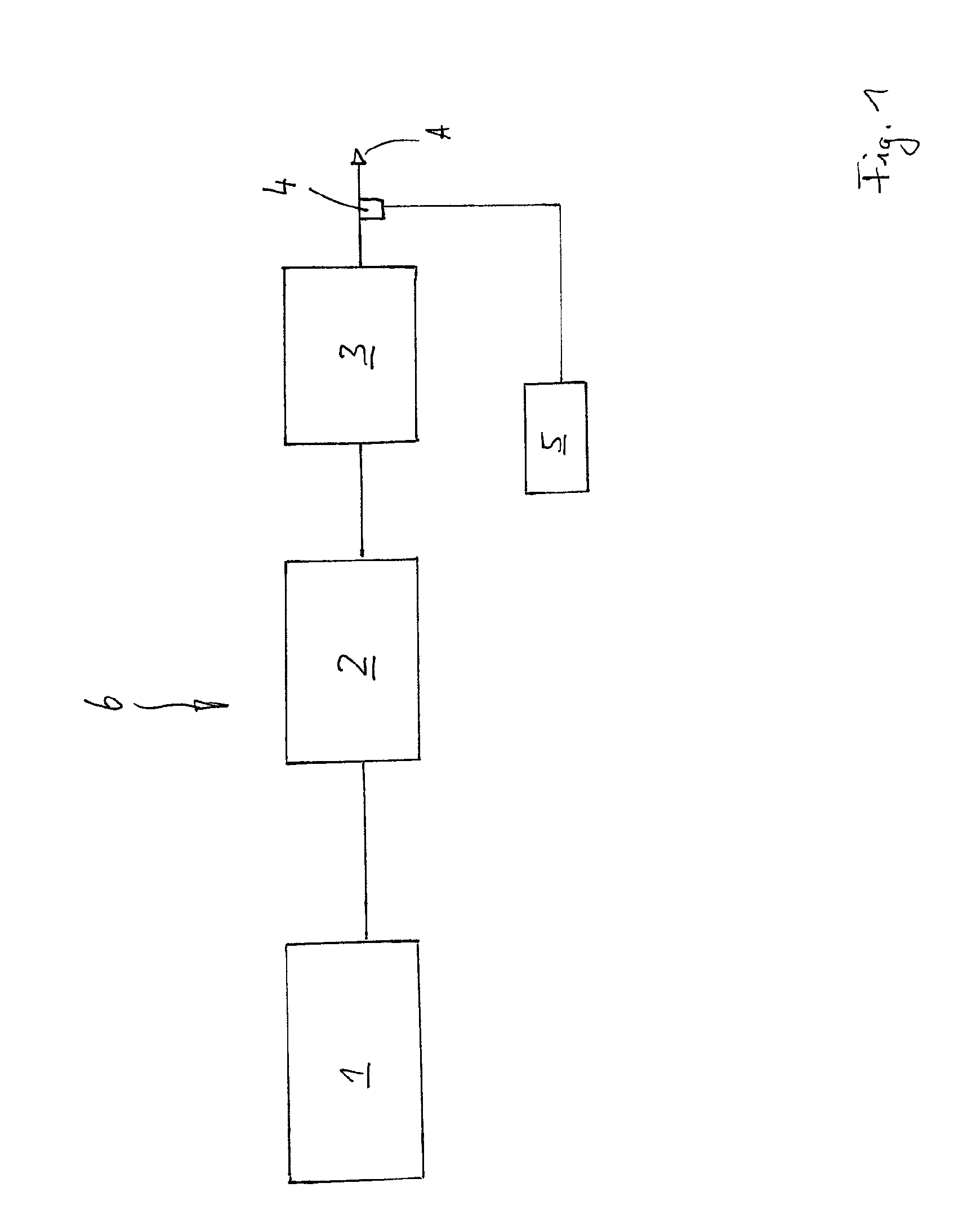
[0023]FIG. 1 shows a principal representation of a common exhaust-system branch 6 with a combustion engine 1, which operates, for example, according to the Diesel principle, and is, when seen in flow direction A, arranged downstream of an oxidation catalyst 2, a carbon particle filter 3 and a carbon monoxide sensor 4, which is connected to a control device 5 for monitoring the sensor signals. The combustion engine can also be a lean operated Otto-engine (petrol engine). In the manner, which is not described in more detail, but generally known, the control device is at least part of a system for the on-board-diagnosis (OBD). The carbon particle filter 3 is provided with a catalytic coating on its inside, which is not shown in detail in FIG. 1 because of the principal representation.

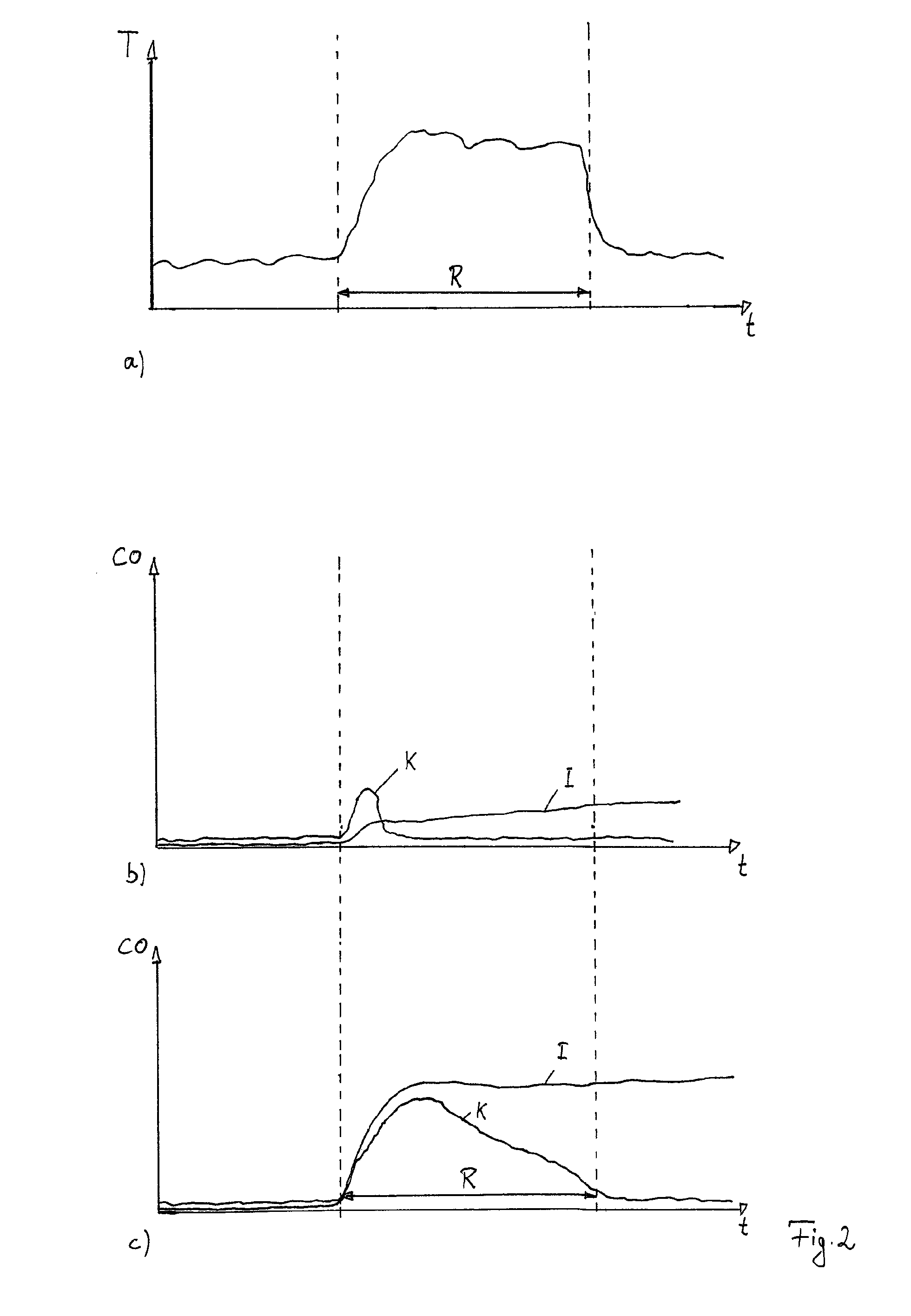
[0024]Furthermore, a possibility for the temperature measurement can be provided downstream of the oxidation catalyst 2. Thus, a diagnosis of the oxidation catalyst 2 is achieved by evaluating a temperatur...


PUM


Abstract

Method for the on-board diagnosis of an exhaust gas post-treatment device for a combustion engine, wherein the exhaust gas post-treatment device has means for converting an exhaust gas component and wherein sensor means are provided downstream of the exhaust gas post-treatment device, wherein the exhaust gas component is acquired by the sensor means and that by means of the quantity of the acquired exhaust gas component the quality of the means for converting the exhaust gas component is derived, wherein a signal of the sensor means is transmitted to a system for the on-board diagnosis.

Description

CROSS-REFERENCE TO RELATED APPLICATIONS[0001]This application claims priority of German Patent Application No. 102011000153.0 filed on Jan. 14, 2011, which is incorporated herein in its entirety by reference.FIELD OF THE INVENTION[0002]The invention relates to a method for the on-board diagnosis of an exhaust gas post-treatment device for a combustion engine, wherein the exhaust gas post-treatment device has means for converting an exhaust gas component and wherein sensor means are provided downstream of the exhaust gas post-treatment device.BACKGROUND OF THE INVENTION[0003]The State of the Art is, that a carbon particle filter stores soot in the so-called adsorption operation. Carbon particle filters are also called Diesel particulate filters (DPF). When the particle filter cannot absorb any further soot, it has to be cleaned by a regeneration. For this, different measures are available, whereof one is, for example, to additionally heat the exhaust gas by corresponding measures, so...

Claims


Application Information

Patent Timeline
IPC IPC(8): F01N11/00F01N3/035
CPCF01N3/035F01N11/002F01N2550/02F01N2550/04Y02T10/47F02D41/0235F02D2041/228F02D41/029F02D41/1439F02D41/1452F02D41/1454F02D41/146F02D41/401F02D41/025Y02T10/40
Inventor SEVERIN, CHRISTOPHERSCHONEN, MARKUS
Owner FEV
Why Eureka
Eureka Blog
Learn More