Humidifier for Fuel Cell Systems

Active Publication Date: 2012-07-19
DANA CANADA CORP
View PDF3 Cites 58 Cited by
  • Summary
  • Abstract
  • Description
  • Claims
  • Application Information

AI Technical Summary

Problems solved by technology

Technical challenges in planar humidifiers include achievement of high surface area exposure of the membranes to the exchange gases at controlled fluid flow rates, meaning that tightly packed and very small and consistent repeat cell (plate to membrane) distances are necessary; and in conjunction with reliably sealed membrane-to-plate, and plate-to-plate joints.

Method used


Image

  • Humidifier for Fuel Cell Systems
  • Humidifier for Fuel Cell Systems
  • Humidifier for Fuel Cell Systems

Examples


first embodiment

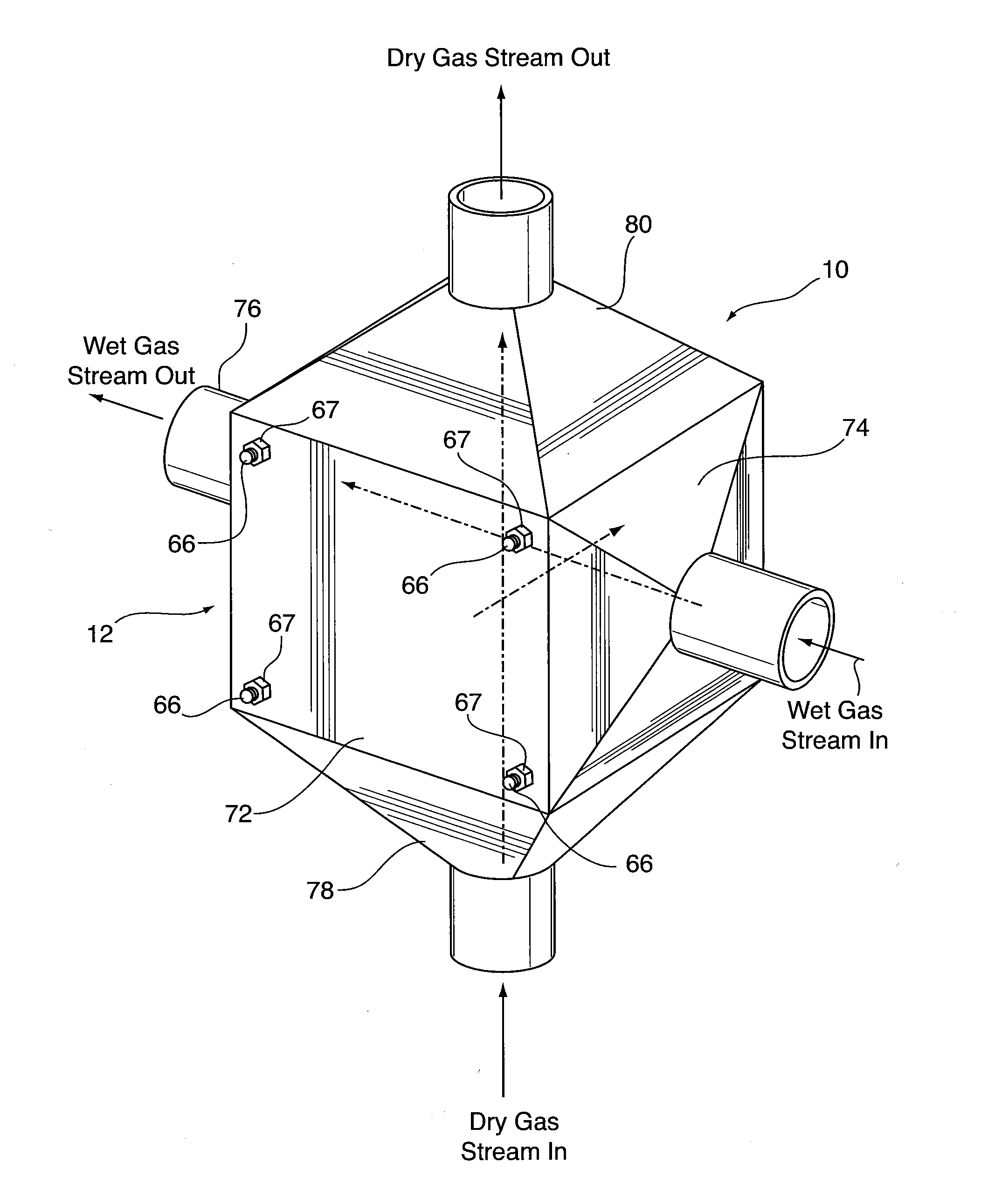
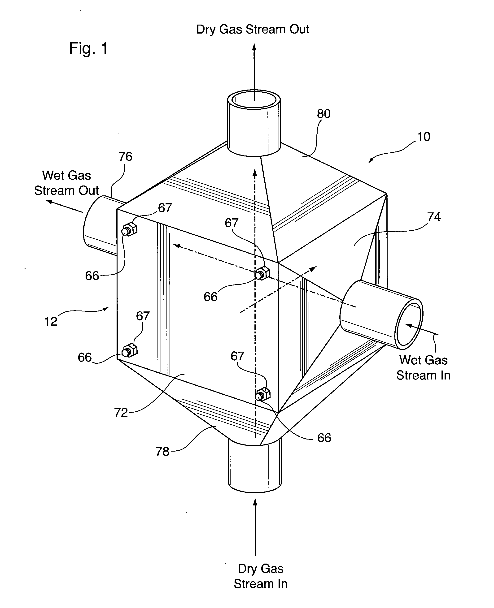
[0047]Illustrated in FIGS. 1 to 8 is a humidifier 10 according to a Humidifier 10 is made up of a core 12 comprising a stack of plates, further described below, and two pairs of manifolds located external to the core 12. In the following description, the terms “core” and “stack” are used interchangeably.

[0048]The core 12 has a total of six faces, with the wet gas stream entering the core 12 through one of its faces and exiting the core 12 through an opposite face. Similarly, the dry gas stream enters the core 12 through one of its faces and exits the core 12 through an opposite face. The remaining two faces are not involved in water exchange, but serve as mechanical fixturing surfaces for compression assembly of the humidifier stack between a pair of structural end plates 72, 173, as further described below and illustrated in FIG. 7.

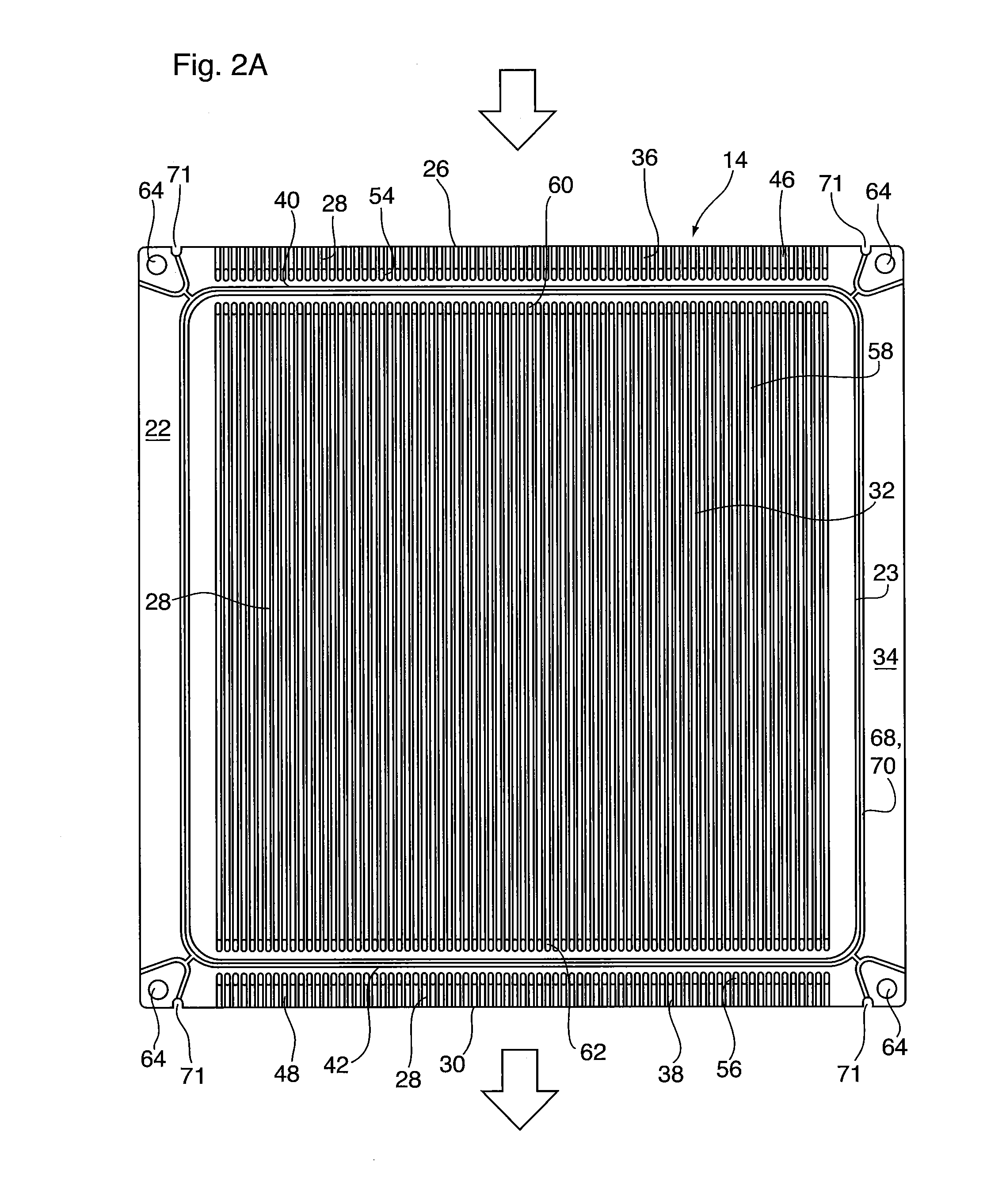
[0049]The core 12 of humidifier 10 comprises a plurality of wet plates 14 and a plurality of dry plates 16 stacked in alternating order throughout the ...

second embodiment

[0093]A humidifier 110 is now described below with reference to FIGS. 9 and 10. Humidifier 110 is identical to humidifier 10 above in all respects, except for the differences noted below, and therefore the description of the elements of humidifier 10 applies equally to humidifier 110, unless otherwise stated. Also, in the drawings and in the following description, like elements of humidifiers 10 and 110 are identified by like reference numerals.

[0094]The humidifier 110 according to the second embodiment comprises a core 12 which is constructed from wet and dry plates 14, 16, membranes 18 and gas diffusion layers 20. The wet and dry plates 14, 16 used in the core 12 of humidifier 110 are identical in all respects to the wet and dry plates 14, 16 of humidifier 10, except for the construction of the flow field 32. In humidifier 110, the flow fields 32 of the plates 14, 16 are traversed by support ribs 28, and adjacent ribs 28 are connected by webs 82. In contrast to the elongate webs ...

third embodiment

[0096]A humidifier 210 is now described below with reference to FIGS. 11-15. Humidifier 210 is a cross-flow humidifier and is identical to humidifier 10 in all respects, except as noted below. Therefore the description of the elements of humidifier 10 applies equally to humidifier 210, unless otherwise stated. Also, in the drawings and in the following description, like elements of humidifiers 10 and 210 are identified by like reference numerals.

[0097]Humidifier 210 differs from humidifier 10 in that the inlet and outlet manifolds for the wet and dry gases are integrally formed as part of the core 12. This avoids the need to provide separately formed, external manifolds 74, 76, 78, 80 which must be sealed to the core. In order to provide integral manifolds, each wet and dry plate 14, 16 making up humidifier 210 includes manifold openings which, when the plates 14, 16 are stacked, will form the respective inlet and outlet manifolds for the wet and dry gas streams. The plates 14, 16 ...


PUM

PropertyMeasurementUnit
thicknessaaaaaaaaaa
thicknessaaaaaaaaaa
thicknessaaaaaaaaaa

Abstract

A humidifier for a fuel cell system comprises a stack of thin plates having planar sealing surfaces at their edges. A water permeable membrane is provided between each pair of plates. Each plate defines a gas flow passage along its top and bottom surfaces, with an inlet and outlet defined along edges of the plate, and a flow field extending between the inlet and outlet openings. Inlet and outlet passages connect the inlet and outlet openings to the flow field, and the planar sealing surfaces on both sides of the plate include bridging portions which extend across the inlet and outlet passages. Support structures are provided throughout the flow field and the inlet and outlet passages to support the membrane and diffusion medium layer(s). The support structures may optionally be connected together by webs having holes for flow distribution between the top and bottom of each plate.

Description

CROSS-REFERENCE TO RELATED APPLICATION[0001]This application claims priority to and the benefit of U.S. Provisional Patent Application No. 61 / 432,429 filed Jan. 13, 2011, the content of which is incorporated herein by reference.FIELD OF THE INVENTION[0002]The invention relates to humidifiers for humidifying a reactant gas in a fuel cell system.BACKGROUND OF THE INVENTION[0003]Fuel cell systems generate electrical power from an electrochemical reaction between a fuel and an oxidant. Many fuel cell systems use a gaseous fuel, such as molecular hydrogen, and a gaseous oxidant such as molecular oxygen contained in air. The reaction between hydrogen and oxygen generates water which is exhausted in the waste gases of the fuel cell.[0004]Many fuel cells, and especially fuel cells used for automotive propulsion, are based on proton exchange membrane (PEM) technology. These fuel cells contain PEM membranes that operate at about 80° C., and which must be kept moist for optimal performance and...

Claims


Application Information

Patent Timeline
Patent Type & Authority Applications(United States)
IPC IPC(8): F24F3/14
CPCF24F2003/1435H01M8/04074Y02E60/50H01M8/04149H01M8/04141F24F6/00F28F3/08F28F3/12H01M8/04
Inventor VANDERWEES, DOUGHASAN, MANAFWILSON, JONKUMMEROW, JACK
Owner DANA CANADA CORP
Why Eureka
Try Eureka