DC power supply apparatus

a technology of power supply apparatus and power supply line, which is applied in the direction of electric variable regulation, process and machine control, instruments, etc., can solve the problems of power supply from the commercial power line system that may leak to the ground and reduce the efficiency of power conversion, and achieve the effect of improving high power conversion efficiency

Active Publication Date: 2012-07-19
NIPPON SOKEN +1
View PDF0 Cites 70 Cited by
  • Summary
  • Abstract
  • Description
  • Claims
  • Application Information

AI Technical Summary

Benefits of technology

[0009]It is therefore an object to provide a DC power supply apparatus, which has an improved high power conversion efficiency.

Problems solved by technology

The power supplied from the commercial power line system may leak to the ground through the stray capacitances.
The switching circuit and the insulating converter however lowers efficiency of power conversion.

Method used


Image

  • DC power supply apparatus
  • DC power supply apparatus
  • DC power supply apparatus

Examples


first embodiment

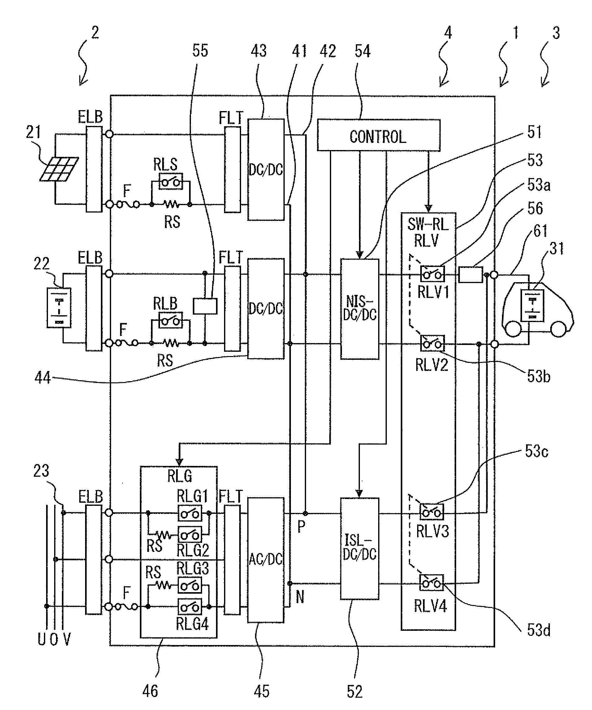
[0028]Referring to FIG. 1, a charging system 1 includes a DC power supply apparatus according to a first embodiment. The charging system 1 includes one or plural power source devices 2, one or plural load devices 3 and a charging circuit 4, which is a conversion circuit for converting power supplied from each power source device 2. Power supplied from the power source device 2 is converted to DC power of a predetermined voltage by the charging circuit 4 and supplied to the load device 3. The charging system 1 may be formed for a house, a housing complex or a charging station, which is provided for charging an unspecified number of load devices.

[0029]Each power source device 2 supplies power of a predetermined power source voltage. The power source device 2 may be a DC power source for supplying DC power or an AC power source for supplying AC power. The DC power source includes a solar power generator 21 and a stationary type secondary battery 22. The AC power source includes a comme...

second embodiment

[0069]In a DC power supply apparatus according to a second embodiment, as shown in FIG. 9, a charging circuit (conversion circuit) 204 is configured to charge secondary batteries 31 and 231 of two vehicles at the same time. The charging circuit 204 includes first cables 61 and second cables 261.

[0070]A switching relay (SW-RL) 253 includes single-throw double-pole relays (RLV1, RLV2, RLV3 and RLV4) 253a, 253b, 253c and 253d, which form the system relay RLV. The relays 253a, 253b, 253c and 253d connect the non-insulating converter circuit 51 and the insulating converter circuit 52 switchably to the first cables 61 and the second cables 261. The relays 253a, 253b, 253c and 253d connect the insulating converter circuit 52 and the second cables 261 when the insulating converter circuit 52 is connected to the first cables 61. The relays 253a, 253b, 253c and 253d connect the non-insulating converter circuit 51 and the second cables 261 when the insulating converter circuit 52 is connected ...

third embodiment

[0076]In a DC power supply apparatus according to a third embodiment, as shown in FIG. 10, a charging circuit (conversion circuit) 304 includes a switchable converter circuit 351 in place of the non-insulating converter circuit 51 and the insulating converter circuit 52, which are provided in the first and the second embodiments. The switchable converter circuit 351 is selectively switchable to a non-insulating circuit and an insulating circuit. The switchable converter circuit 351 is a switchable DC power conversion circuit (NIS-ISL-DC / DC). The switchable converter circuit 351 includes a part, which is provided as the insulating converter circuit, and a switching relay (SW-RL) 353, which is provided as a switching device. The system relay RLV includes two relays RLV1 and RLV2. A control circuit 354 controls the breaker relay 46 to disconnect the commercial power line system 23 from the charging circuit 304 and also controls the switching relay 353 to switch over the switchable conv...


PUM


Abstract

A DC power supply apparatus includes a charging circuit, which charges a secondary battery of a vehicle from an AC power source device or a DC power source device. The charging circuit includes a non-insulating converter circuit and an insulating converter circuit. A breaker relay disconnects the AC power source device and the charging circuit in an initial charging period to supply a large charging current to the secondary battery by the non-insulating converter circuit. As a result, charging can be performed with high efficiency without the insulation transformer. The breaker relay connects the AC power source device and the charging circuit after the initial charging period. Only the insulating converter circuit supplies the charging current to the secondary battery. Thus, adverse effect of stray capacitance of a circuit of the vehicle can be eliminated.

Description

CROSS REFERENCE TO RELATED APPLICATION[0001]This application is based on and incorporates herein by reference Japanese patent application No. 2011-9082 filed on Jan. 19, 2011.TECHNICAL FIELD[0002]The present invention relates to a DC power supply apparatus, which supplies DC power and may be used, for example, in a charging system for charging a secondary battery.BACKGROUND ART[0003]The following patent documents disclose an insulation type DC power conversion circuit (referred to as an insulation type DC / DC converter or an insulating converter), the primary side and the secondary side of which are insulated by an insulating transformer. The insulating converter is effective to suppress ground leakage of current.[0004]Patent document 1: JP H07-298513A[0005]Patent document 2: JP 2008-312382A[0006]Patent document 3: JP 2009-33800A (US 2009 / 0034300A1)[0007]Patent document 4: JP 4527616[0008]In a battery charging system, in which a DC power supply apparatus may be used, a secondary batt...

Claims


Application Information

Patent Timeline
Patent Type & Authority Applications(United States)
IPC IPC(8): H02J7/00H02M3/335
CPCB60L11/1811H02J1/102H02J7/02Y02T10/92Y02T10/7005Y02T90/14Y02T90/127H02M3/28B60L53/11B60L53/20B60L53/30B60L53/53Y02T10/70Y02T10/7072Y02T90/12H02J5/00
Inventor ASAKURA, FUMIOOCHI, KENJIYOSHIDA, HIROSHI
Owner NIPPON SOKEN
Why Eureka
Try Eureka