
Cell packaging material and method for manufacturing same

a technology of cell packaging and cell components, applied in cell components, jackets/cases materials, thermography, etc., can solve the problems of increased manufacturing cost, limited marking of various logos, shapes, etc., and achieve distinguishability or exterior design. , improve the effect of productivity

Active Publication Date: 2012-07-19
YOULCHON CHEM
View PDF3 Cites 19 Cited by
  • Summary
  • Abstract
  • Description
  • Claims
  • Application Information

AI Technical Summary

Benefits of technology

The present invention provides a cell packaging material and a method for manufacturing the material, which can protect cells safely and easily have distinguishability and exterior design without the need for a separate labeling operation. The material is made by removing a portion of the base film layer or printing layer using laser irradiation, allowing for various shapes and patterns to be easily realized. The material is also lightweight, flexible, and has excellent heat resistance, electric insulation, moisture-proof, and gas barrier properties. The manufacturing process is efficient and cost-effective. The material can be obtained in a short time, has low weight, and can be provided in various shapes and colors.

Problems solved by technology

However, such metallic can packaging materials have a hard outer wall and thus have a limitation that the shape of a cell to be packaged is determined by the shape of metallic can packaging materials.
Such a separate labeling operation has the problems of delayed production and increased manufacture cost.
In addition, since labels that have been used to date are those obtained by printing bar codes, etc., through a dot printing process, there have been limitations in marking various logos, shapes, or the like.

Method used


Image

  • Cell packaging material and method for manufacturing same
  • Cell packaging material and method for manufacturing same

Examples


experiment 1

Evaluation of Characteristics of Cell Packaging Materials Depending on Particle Diameter of Carbon Black

example 1

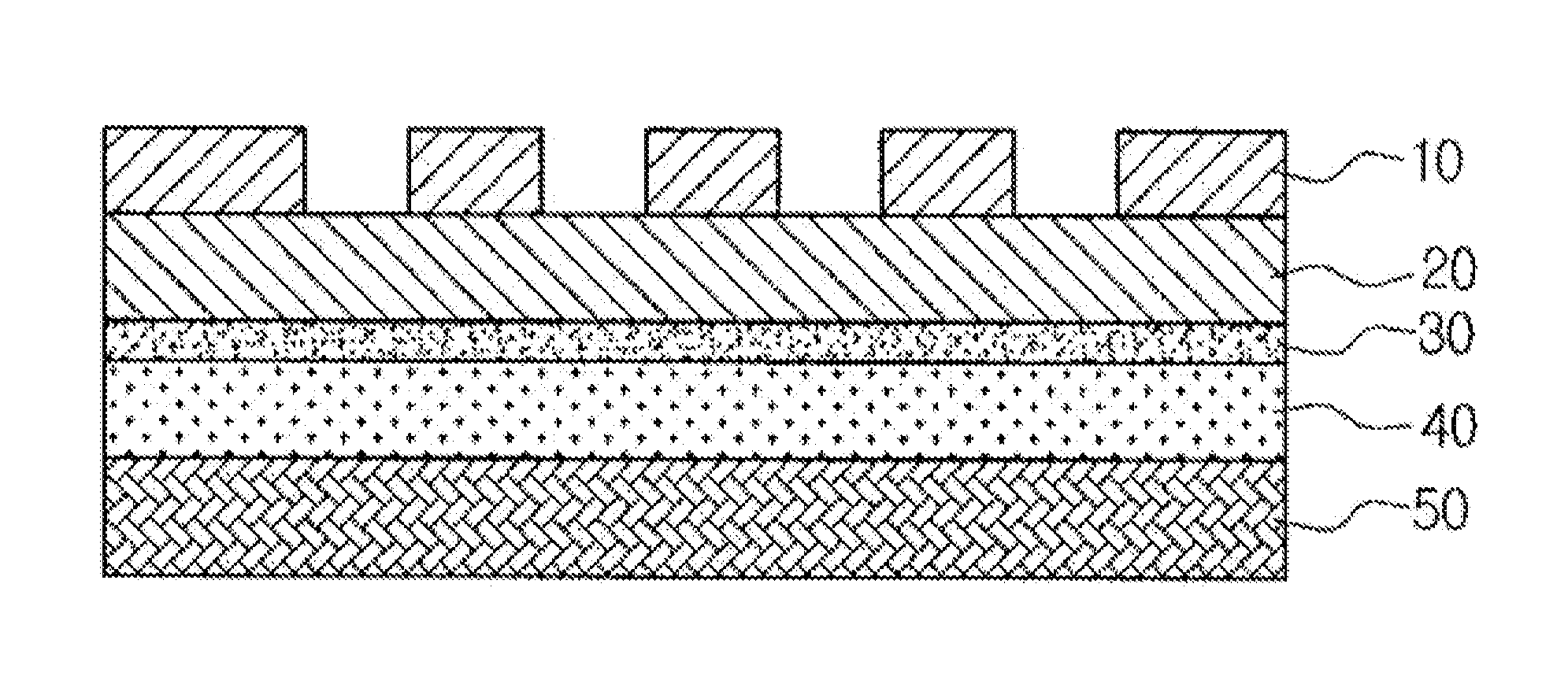
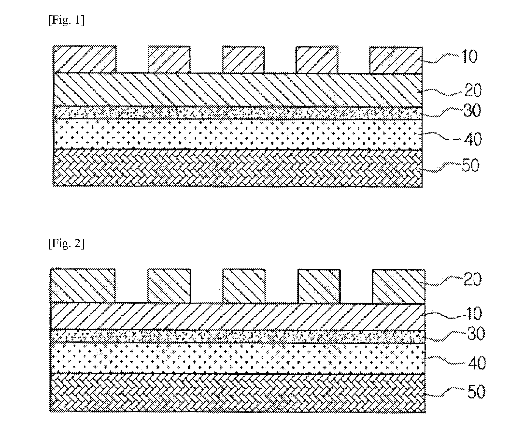
[0078]A cell packaging material having a structure of printing layer / base film layer / adhesive layer / barrier layer (aluminum foil) / melt extrusion resin layer / sealant layer is provided.

[0079]The printing layer includes 10 wt % of a polyurethane resin and 10 wt % of carbon black having a particle diameter of 3 μm. The base film layer consists of a nylon resin and the adhesive layer consists of a polyester resin. The melt extrusion resin layer consists of a polypropylene resin. The sealant layer consists of a terpolymer of ethylene, propylene and butadiene.

Comparative Examples

[0080]Cell packaging materials are provided in the same manner as Example 1, except that carbon black having a particle diameter of 7 μm (Comp. Ex. 1) or 11 μm (Comp. Ex. 2) is used in the printing layer.

[0081]Printing Transferability

[0082]The cell packaging materials are cut into a size of 1 m×1 m to provide samples. Then, the number of non-printed portions in the printing layer of each sample is determined by the...

experiment 2

Evaluation of Characteristics of Cell Packaging Materials Depending on Binder Resin Content in Printing Layer


PUM

PropertyMeasurementUnit
particle diameteraaaaaaaaaa
thicknessaaaaaaaaaa
thicknessaaaaaaaaaa

Abstract

Cell packaging according to one embodiment of the present invention comprises: a base film layer; and a print layer provided beneath or on the base film layer, and including a binder resin and carbon black. The base film layer or print layer of the cell packaging is partially removed by means of laser irradiation to expose the layer under same. Therefore, according to the cell packaging of the invention, a wide range of shapes or logos, etc. can easily be externally displayed so as to be discernible by means of laser irradiation. By thus imparting discernibility and externality to the cell packaging, a labeling process for attaching a separate label to the cell packaging can be excluded.

Description

TECHNICAL FIELD[0001]The present invention relates to a cell packaging material for lithium secondary batteries or portable storage batteries, and a method for manufacturing the same. In particular, the present invention relates to a cell packaging material including a base film layer or printing layer removed partially by laser irradiation, and to a method for manufacturing the same.BACKGROUND ART[0002]In general, packaging materials obtained by pressing metal, particularly aluminum, and forming it into a cylindrical or parallelepiped shape have been used as cell packaging materials for lithium secondary batteries, portable storage batteries or the like. However, such metallic can packaging materials have a hard outer wall and thus have a limitation that the shape of a cell to be packaged is determined by the shape of metallic can packaging materials.[0003]To overcome such a limitation, laminate cell packaging materials have been developed. For example, Korean Patent Application No...

Claims


Application Information

Patent Timeline
Patent Type & Authority Applications(United States)
IPC IPC(8): H01M2/02B32B5/16B32B3/10B32B1/00B32B7/023H01M50/121H01M50/124H01M50/133H01M50/134H01M50/143
CPCB41M5/24Y10T428/24876H01M2/0275H01M2/0287H01M2/0295H01M2/1094H01M2/344B41M5/34B32B27/36B32B7/12B32B7/02B32B27/30B32B27/08B32B27/40B32B27/38Y10T428/24901B65D2203/02Y10T428/24893Y10T428/2495Y10T428/25Y10T428/265Y02E60/10H01M50/124H01M50/24H01M50/598B32B7/023H01M50/133H01M50/121H01M50/134H01M50/143
Inventor KANG, HAN JUNHAN, HEE SIKJUNG, WOO SICLEE, SUNG HOYOON, JONG WOONKIM, JI HEELEE, SANG MIN
Owner YOULCHON CHEM
Learn More