Vial assemblage with vial and pre-attached fluid transfer device

a fluid transfer device and assemblage technology, applied in the field of vial assemblages, can solve the problems of introducing a margin of error in the procedure, multiple steps take considerable preparation time, etc., and achieve the effect of reducing the likelihood of inadvertent inclination of the fluid transfer device and reducing the thickness

Inactive Publication Date: 2012-07-19
MEDIMOP MEDICAL PROJECTS
View PDF0 Cites 69 Cited by
  • Summary
  • Abstract
  • Description
  • Claims
  • Application Information

AI Technical Summary

Benefits of technology

[0005]Fluid transfers device are manually urged from an initial non-communication set-up position to a flow communication position. Fluid transfer devices preferably include a flow member arrest arrangement for stopping displacement of a flow member towards a vial on manual urging to its flow communication position such that its spike end protrudes a predetermined distance into a vial interior for flow communication purposes. Fluid transfer devices also preferably include a flow member securing arrangement for preventing manual removal of a closure inadvertently withdrawing a flow member from its blind bore. In the case of a screw cap, flow member securing arrangements prevent rotation of the flow member relative to the stopper during unscrewing of the screw cap and screwing a syringe onto the connector.
[0007]Vial assemblages of the present invention afford convenient and sterile liquid drug reconstitution precluding the initial preparation steps of a vial and a vial adapter and the subsequent assembly steps of aligning a vial adapter with a vial before snap fitting the former on the latter. Moreover, by virtue of the stoppers having a considerably reduced thickness at their bore ends compared to conventional stoppers, the pre-inserted spikes are ensured to puncture through the stoppers to achieve flow communication with the vial interiors. Furthermore, the blind bores act to guide their pre-inserted spikes during aforesaid manual depression thereby reducing the likelihood of inadvertent inclination of a fluid transfer device with respect to a vial.

Problems solved by technology

Such multiple steps take considerable preparation time and introduce a margin for error in the procedure.
Moreover, many users inadvertently misalign the vial adapter with the vial such that the former's cannula is unable to puncture the vial's stopper for flow communication purposes.

Method used


Image

  • Vial assemblage with vial and pre-attached fluid transfer device
  • Vial assemblage with vial and pre-attached fluid transfer device
  • Vial assemblage with vial and pre-attached fluid transfer device

Examples


Embodiment Construction

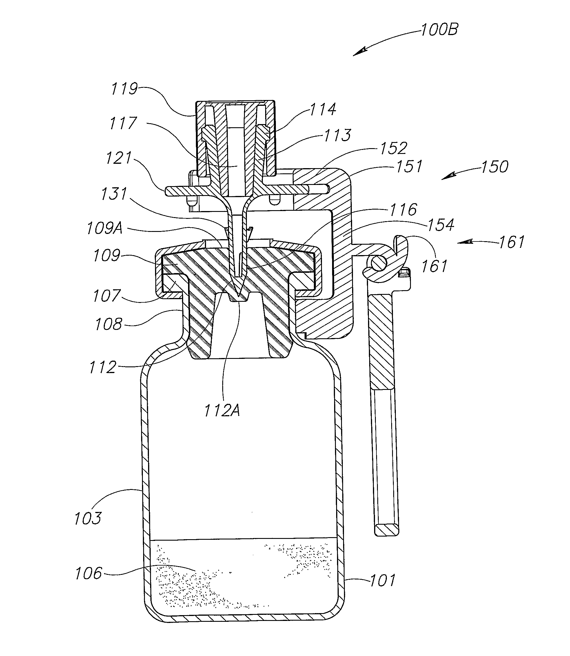
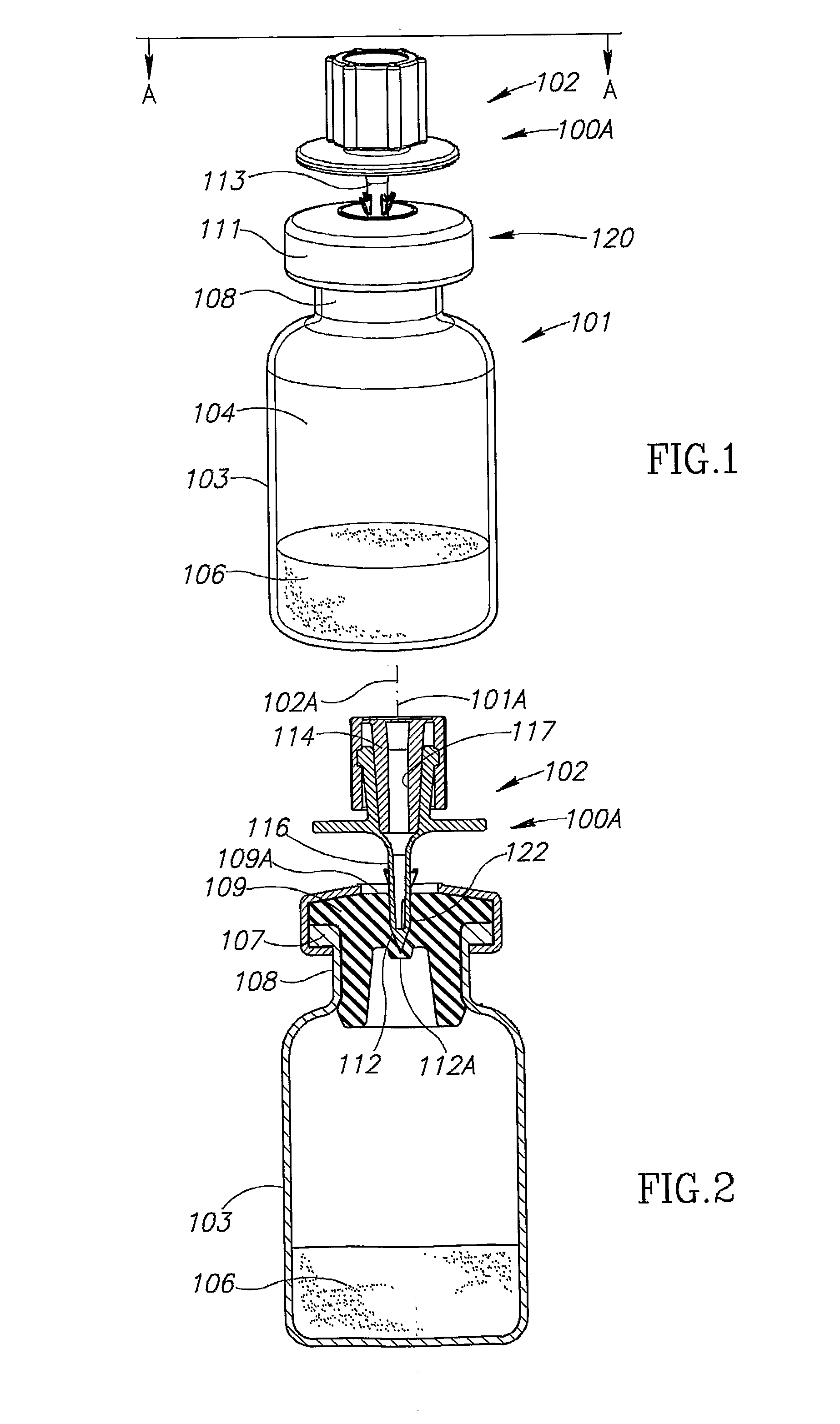
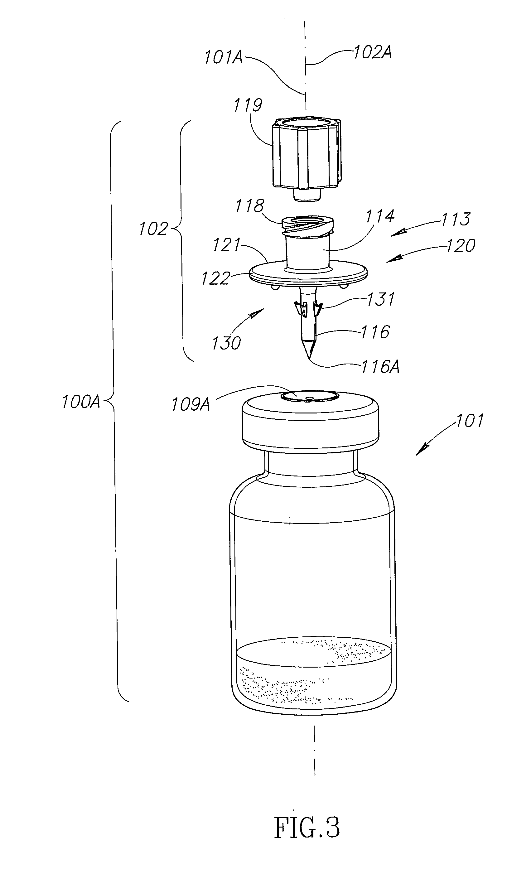
[0025]FIGS. 1 to 5 show a vial assemblage 100A having a two part construction including a vial 101 and a pre-attached fluid transfer device 102. The vial 101 has a longitudinal axis 101A and includes a vial body 103 having a vial interior 104 for storing a powdered or liquid medicament 106, a vial rim 107 defining a vial opening, and an intermediate narrow diameter vial neck 108 between the vial interior 104 and the vial rim 107. The vial 101 is sealed by a stopper 109 having an exposed uppermost stopper surface 109A. The vial 101 is hermetically sealed by a band 111. The stopper 109 is formed with a blind bore 112 with a bore end 112A of reduced stopper thickness between the bore end 112A and the vial interior 104.

[0026]The fluid transfer device 102 has a longitudinal axis 102A substantially co-axial with the longitudinal axis 101A and includes an elongated tubular flow member 113. The flow member 113 includes a connector 114, a spike 116, and a single lumen 117 extending lengthwis...


PUM


Abstract

Vial assemblages having a vial and a pre-attached fluid transfer device for use with a needleless syringe for enabling flow communication between the syringe and the vial. The fluid transfer device includes an elongated tubular flow member having a connector for sealing flow communication with the needleless syringe and a spike having a spike end for puncturing the vial for enabling flow communication between the needleless syringe and vial interior. The spike end is in intimate sealing contact with the vial's stopper. The fluid transfer device also includes a manually removable closure for initially sealing the connector and, on removal, exposing the connector.

Description

FIELD OF THE INVENTION[0001]This invention relates to vial assemblages including a vial with a pre-attached fluid transfer device for use with a needleless syringe.BACKGROUND OF THE INVENTION[0002]Liquid drug reconstitution for reconstitution of medicaments supplied in vials generally involves multiple steps including inter alia opening a vial adapter package for preparing a vial adapter with a cannula for use, preparing a sealed vial for use, co-axial alignment of the vial adapter with the vial and subsequent manually snap fitting the vial adapter onto the vial such that the vial adapter's cannula punctures the vial's stopper. Such vial adapters are commercially available from, for example, Medimop Medical Projects Ltd, Ra'anana, Israel. Such multiple steps take considerable preparation time and introduce a margin for error in the procedure. Moreover, many users inadvertently misalign the vial adapter with the vial such that the former's cannula is unable to puncture the vial's sto...

Claims


Application Information

Patent Timeline
Patent Type & Authority Applications(United States)
IPC IPC(8): A61J1/20
CPCA61J2001/201A61J1/2096A61J2001/2051A61J2001/1425A61J2001/2065A61J1/1406B65D51/002A61J2001/2055A61J1/201A61J1/2055A61J1/1425A61J1/2065A61J1/2051
Inventor LEV, NIMRODBEN SHALOM, NIV
Owner MEDIMOP MEDICAL PROJECTS
Why Eureka
Try Eureka