Method for Damage Diagnosis in a Handheld Work Apparatus

a handheld work and damage detection technology, applied in the direction of electrical control, process and machine control, instruments, etc., can solve the problem of insufficient short operation period, and achieve the effect of simple damage detection option

Inactive Publication Date: 2012-07-19
ANDREAS STIHL AG & CO KG
View PDF10 Cites 1 Cited by
  • Summary
  • Abstract
  • Description
  • Claims
  • Application Information

AI Technical Summary

Benefits of technology

[0011]A simple evaluation results when the determined values for the amount of fuel supplied, the rotational speed and the ignition time are each compared to a set-point value range. It has been shown that the absolute value of the amount of fuel supplied, rotational speed and ignition time are not necessarily required in order to detect damage, but that a comparison with a set-point value range suffices. In particular, the damage is detected via a table stored in the diagnostic unit. The table indicates, in particular, possible damage in dependence on whether the determined values lie in each case within, above or below the set-point value range. As a result, the damage can be detected via a simple matrix.
[0012]In order to determine the amount of fuel supplied in a simple manner, the amount of fuel supplied to the combustion engine is measured out by a metering valve which is connected with the open loop control via a control line, and that the diagnostic unit determines the amount of fuel supplied from the signal in the control line. Thus only a first connection in the ignition line and a second connection in the control line of the metering valve have to be provided in order to determine the amount of fuel supplied, the rotational speed and the ignition time. This results in a very simple option for damage detection. The entire evaluation logic can be provided in the diagnostic unit so that no additional devices for damage detection are necessary on the work apparatus itself.

Problems solved by technology

It has been shown that only a short period of operation is sufficient for damage diagnosis for many types of damage that occur in a handheld work apparatus.

Method used


Image

  • Method for Damage Diagnosis in a Handheld Work Apparatus
  • Method for Damage Diagnosis in a Handheld Work Apparatus
  • Method for Damage Diagnosis in a Handheld Work Apparatus

Examples


Embodiment Construction

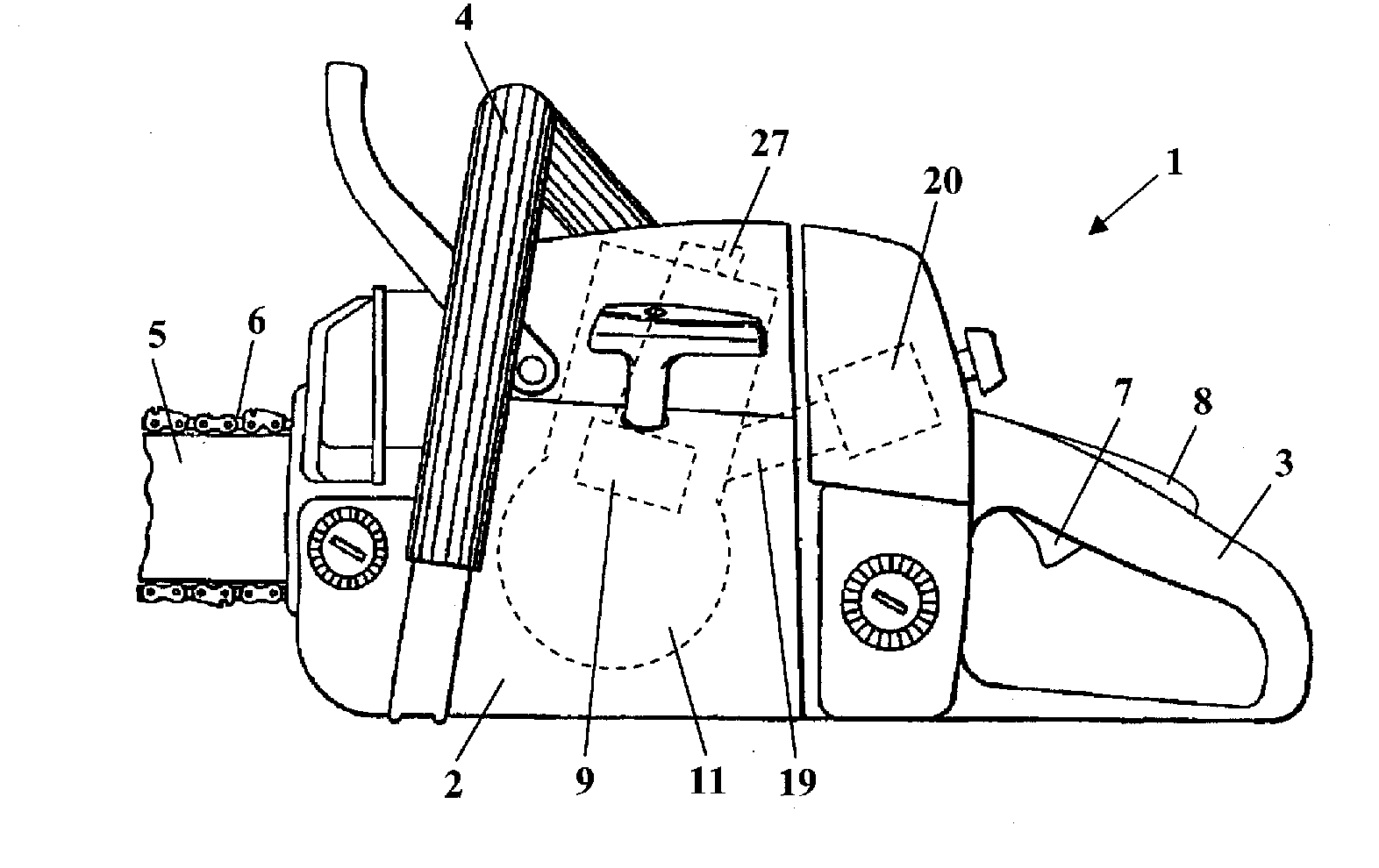
[0021]FIG. 1 shows a chain saw 1 as an exemplary embodiment of a handheld work apparatus. The suggested method, however, can also be utilized in other handheld work apparatus driven by a combustion engine, such as cut-off machines, brushcutters or the like. The chain saw 1 has a housing 2 in which a combustion engine 11 is arranged. The combustion engine 11 has an ignition unit which includes an ignition module 9 and a spark plug 27. An intake channel 19 for the supply of fuel and combustion air, in which fuel is drawn in via a carburetor 20, opens at the combustion engine 11.

[0022]A rear handle 3, on which a throttle lever 7 and a throttle lever lock 8 are pivotably mounted, is arranged on the housing 2 of the chain saw 1. A bale handle 4 extends over the housing 2. Projecting forward on the end of the housing opposite the handle 3 is a guide bar 5, on which saw chain 6, which is driven in circulation by the combustion engine 11, is arranged.

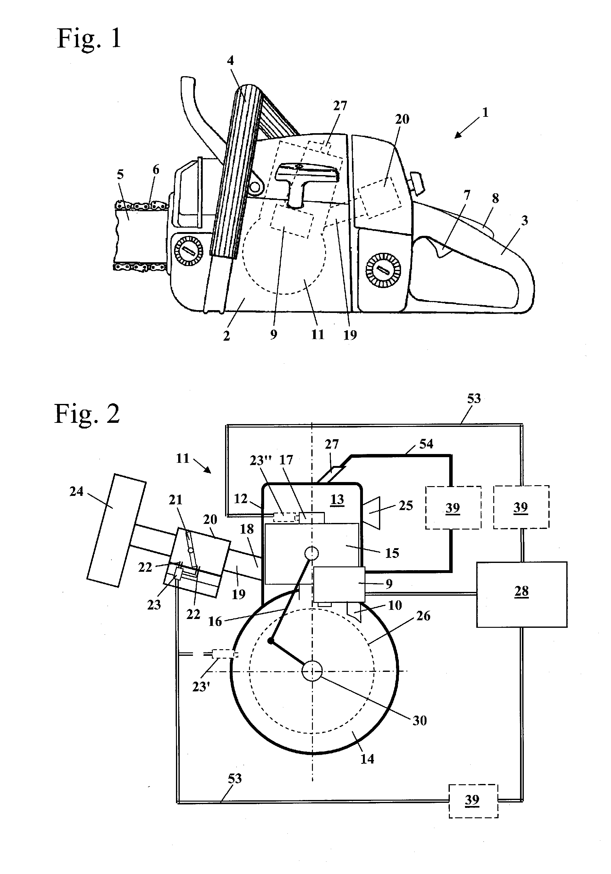
[0023]FIG. 2 shows the combustion engine...


PUM


Abstract

A handheld work apparatus has a combustion engine with an ignition unit, a unit for supplying fuel and a device to determine the rotational speed (n). The ignition unit includes a spark plug, a coil and a pole group. The pole group and the coil are moved in dependence on the rotational movement of a crankshaft of the combustion engine, whereby a ignition voltage is induced in the coil. The work apparatus has an open loop control which controls the ignition time (ZZP). A diagnostic unit for damage diagnosis is detachably connected to the work apparatus. For damage diagnosis, the diagnostic unit captures the course of the induced ignition voltage over at least one engine cycle when the combustion engine is running and damage is determined on the basis of the course of the captured voltage.

Description

CROSS REFERENCE TO RELATED APPLICATION[0001]This application claims priority of German patent application no. 10 2011 008 736.2, filed Jan. 17, 2011, the entire content of which is incorporated herein by reference.FIELD OF THE INVENTION[0002]The invention relates to a method for damage diagnosis in a handheld work apparatus.BACKGROUND OF THE INVENTION[0003]U.S. Pat. No. 7,809,495 discloses a handheld work apparatus which has a data memory. Data stored in the data memory is used to diagnose errors.SUMMARY OF THE INVENTION[0004]It is an object of the invention to provide a method for damage diagnosis in a handheld work apparatus which enables damage diagnosis in a simple manner.[0005]This object is achieved by a method for damage diagnosis in a handheld work apparatus which includes: a combustion engine having an ignition unit, a unit for the supply of fuel, and a device to capture the rotational speed (n); the ignition unit including a spark plug, at least one coil and at least one p...

Claims


Application Information

Patent Timeline
Patent Type & Authority Applications(United States)
IPC IPC(8): F02D28/00F02D41/30
CPCF02D2400/06F02P1/04B25F5/00F02P17/12F02P2017/121F02P1/086
Inventor BOKER, ROBERTSCHMIDT, KARSTEN
Owner ANDREAS STIHL AG & CO KG
Why Eureka
Try Eureka