
Injection control device of internal combustion engine
a technology of injection control device and internal combustion engine, which is applied in the direction of electrical control, process and machine control, instruments, etc., can solve the problems of not being realistic for the present production system, affecting the production efficiency of the engine, and individual differences in characteristics, so as to improve the practicability of the device and increase the injection rate
- Summary
- Abstract
- Description
- Claims
- Application Information
AI Technical Summary
Benefits of technology
Problems solved by technology
Method used
Image

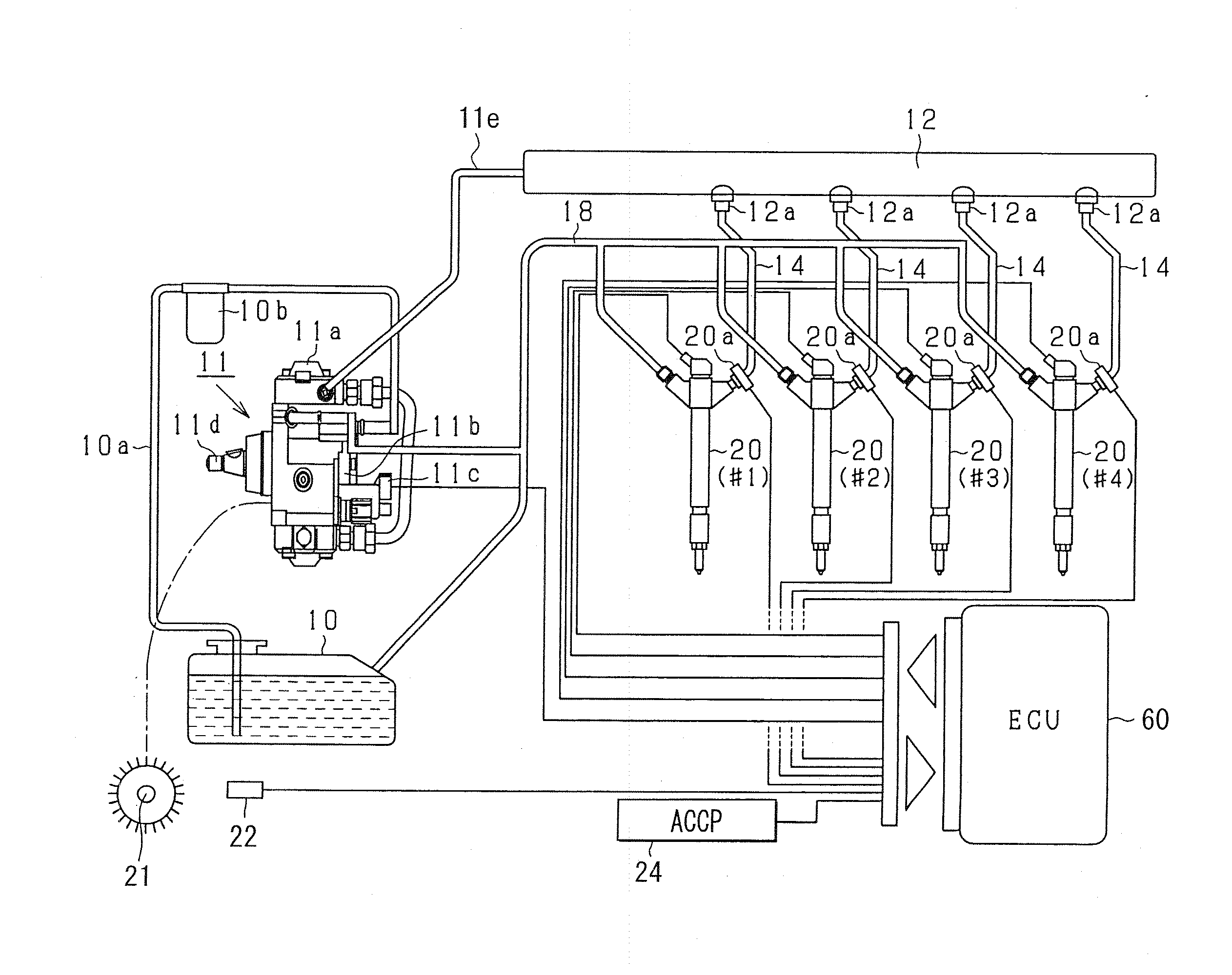
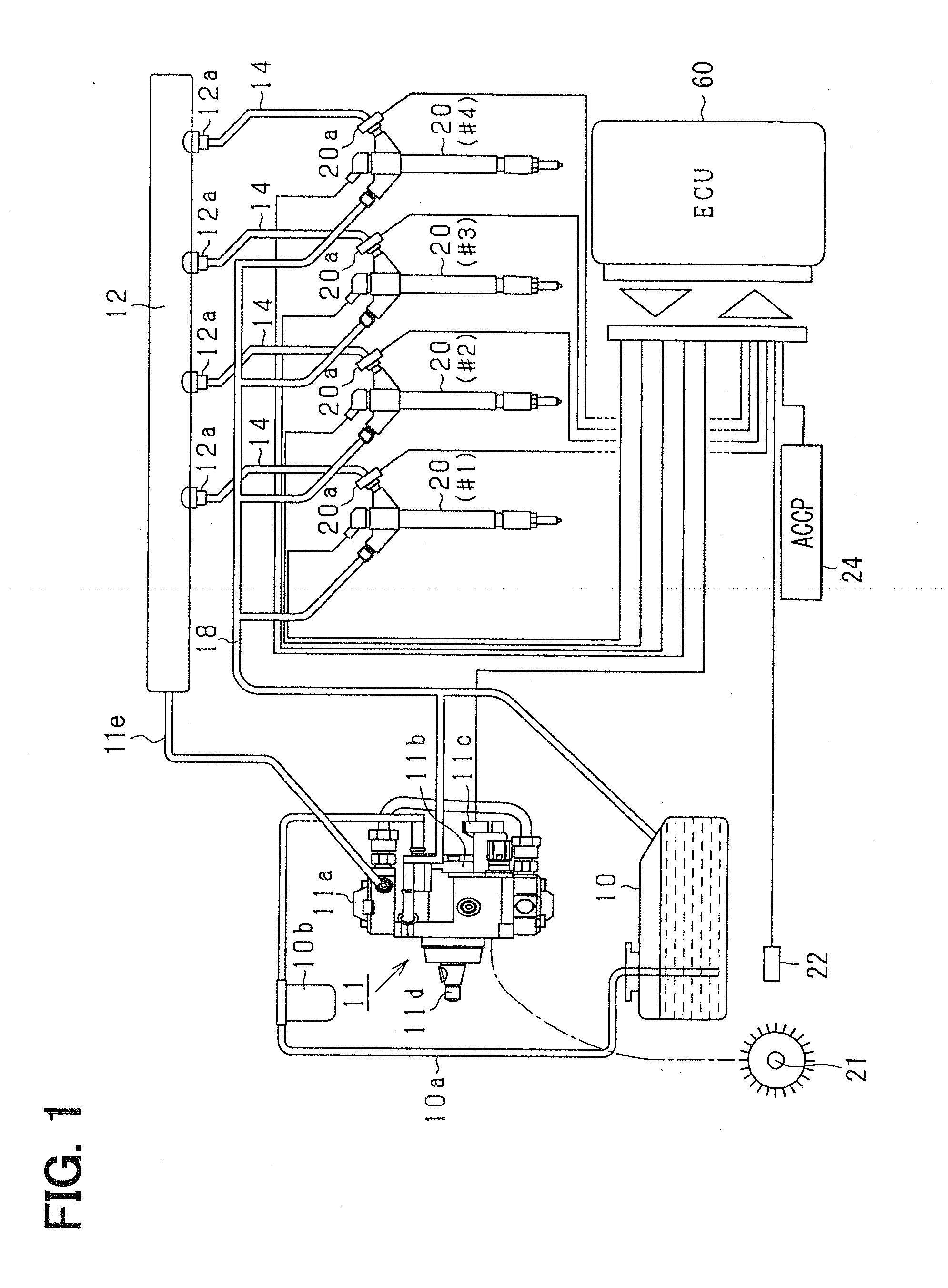
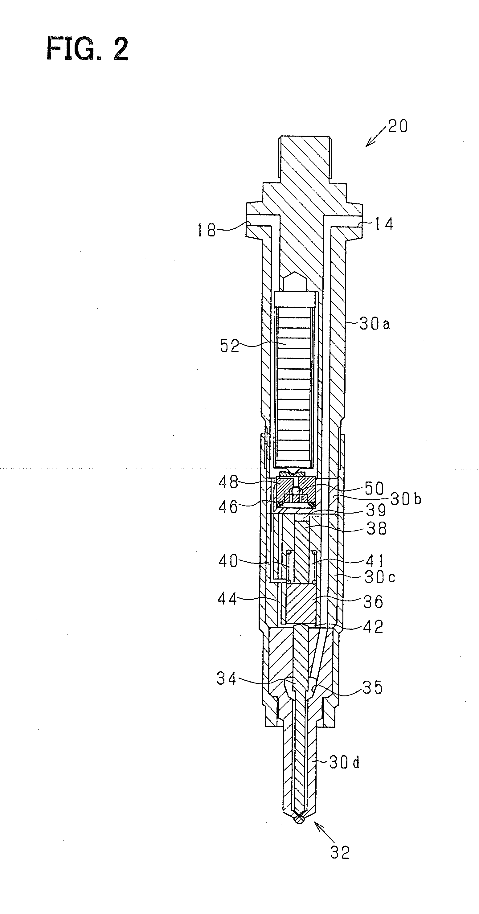
Examples
first embodiment
[0073]A fuel injection device according to the present invention is mounted, for example, in a common rail fuel injection system (a high-pressure injection fuel supply system) for controlling a reciprocating diesel engine as an engine for an automobile. That is, like the device described in Patent document 1, the device according to the present embodiment is also a fuel injection device for a diesel engine used to perform injection supply (direct injection supply) of high-pressure fuel (for example, light oil at injection pressure of 1000 atmospheres or higher) directly into a combustion chamber in an engine cylinder of the diesel engine (an internal combustion engine).
[0074]First, an outline of the common rail fuel injection system according to the present embodiment will be explained with reference to FIG. 1. It is assumed that the engine according to the present embodiment is a multi-cylinder engine (for example, an in-line four-cylinder engine) for a four-wheeled vehicle. The in...
second embodiment
[0147]Next, the present invention will be described.
[0148]In the second embodiment, concerning the injection rate waveform of the actual injection, various timings other than the injection start timing and the injection rates at the timings are also sensed based on the output of the above-described fuel pressure sensor 20a. The injection rate waveform concerning the injection is sensed based on the sensed timings and the injection rates. In addition, the operation current signal, i.e., the operation signal (the actuator operation signal) to the above-described piezoelectric element 52 (FIG. 2), for approximating the sensed injection rate waveform to the above-mentioned basic waveform (part (c) of FIG. 6) is calculated. However, in the present embodiment, the calculated operation current signal is not set during execution of the predetermined injection executed on the occasion of the calculation. That is, the thus-calculated operation current signal is set as a command concerning a c...
PUM
 Abstract
Description
Claims
Application Information