Injection control device of internal combustion engine

a technology of injection control device and internal combustion engine, which is applied in the direction of electrical control, process and machine control, instruments, etc., can solve the problems of not being realistic for the present production system, affecting the production efficiency of the engine, and individual differences in characteristics, so as to improve the practicability of the device and increase the injection rate

Inactive Publication Date: 2009-03-05
DENSO CORP
View PDF21 Cites 40 Cited by
  • Summary
  • Abstract
  • Description
  • Claims
  • Application Information

AI Technical Summary

Benefits of technology

[0011]The inventors noted that a transition of a fuel pressure fluctuation (i.e., a fuel pressure waveform) accompanying a predetermined injection indicates an important characteristic of the injection and invented the above device that senses the fuel pressure waveform and that variably sets the injection command (the injection command signal) to the injector, or more specifically, the actuator operation signal of the valve member of the injector, based on the sensed fuel pressure waveform. With such the device, the characteristic of the target injection can be controlled in a desired mode easily and appropriately based on the fuel pressure waveform. In particular, the device employs the reciprocating drive injector capable of continuously adjusting the fuel injection quantity per unit time (i.e., the injection rate) among the many kinds of the injectors. With such the injector, the injection characteristic of the injector can be precisely controlled based on the injection command to the injector. Moreover, such the injector has been already put in practical use in part, and the practicality thereof has been acknowledged. Therefore, the device according to above aspect of the present invention can perform the appropriate fuel injection control in accordance with the injection characteristic of each time with high practicality.
[0042]The injector of the type that uses the piezoelectric element as the actuator and that can continuously adjust the injection rate is well known. By applying the device according to the above aspects to the injector of such the kind, the practicality of the device is improved. Moreover, with such the injector, the injection rate can be controlled continuously and a boot-shaped injection can be realized, for example. The boot-shaped injection increases the injection rate stepwise in one injection.

Problems solved by technology

However, when mass production and mass marketing of respective components of the engine control system are performed, usually, there occur certain individual differences in characteristics of various kinds of control components including the injector, for example, between the engines and also between the cylinders in the case of a multi-cylinder engine.
In such the case, it takes a lot of works and is not realistic for the present production system to obtain the adaptation values (the optimum injection patterns) for all the components (for example, all the cylinders manufactured through the mass production and mounted in the vehicle) in consideration of also the individual differences.
Therefore, it is difficult to perform the control in consideration of all the influences due to the individual differences even when the map, in which the adaptation values are written, or the mathematical expression is used.
Even if the conventional device such as the device described in Patent document 1 can obtain the optimum value with high accuracy in an initial stage, an influence of the subsequent characteristic change is unknowable.
Therefore, there is a concern that there occurs a deviation from the optimum value with passage of time.
Therefore, it is difficult to thoroughly remove the influence.

Method used


Image

  • Injection control device of internal combustion engine
  • Injection control device of internal combustion engine
  • Injection control device of internal combustion engine

Examples


first embodiment

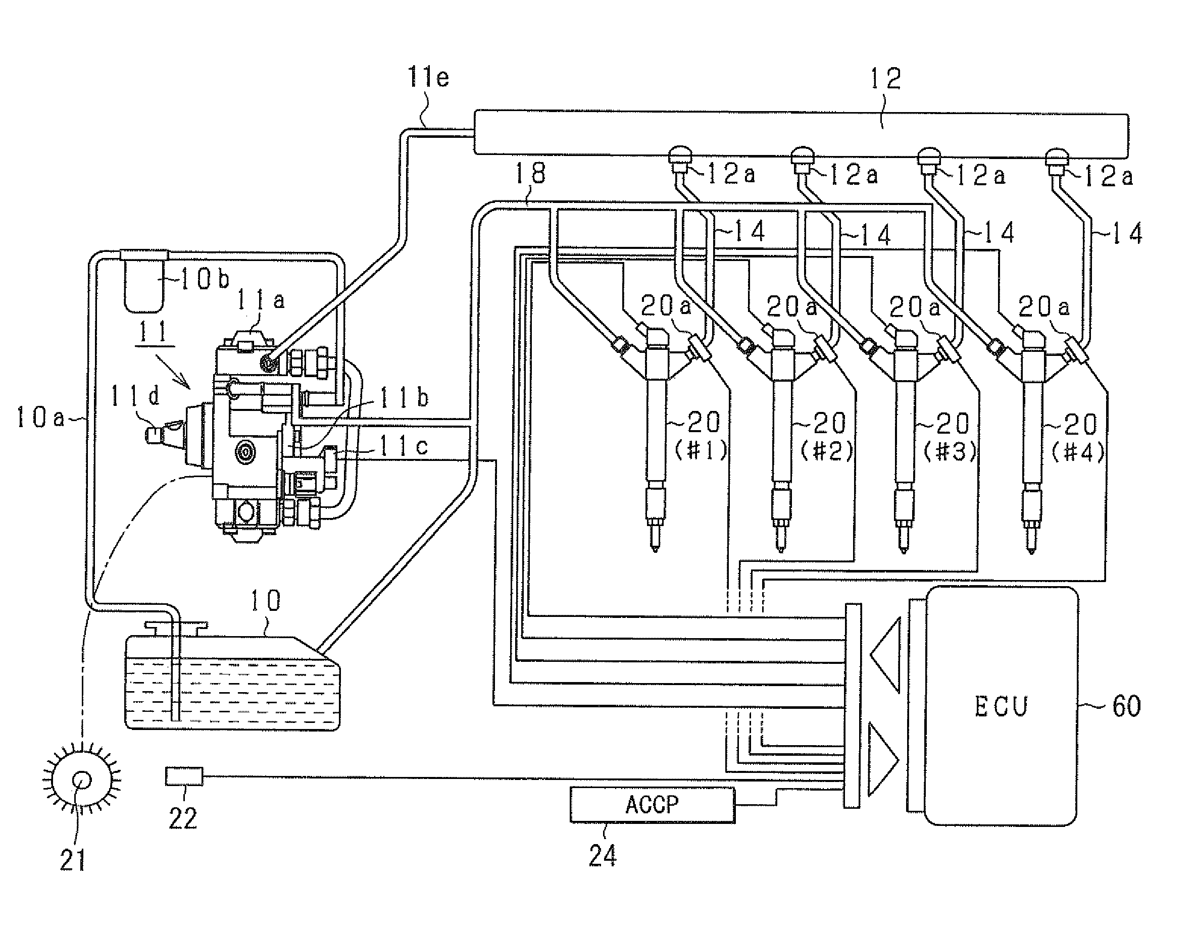
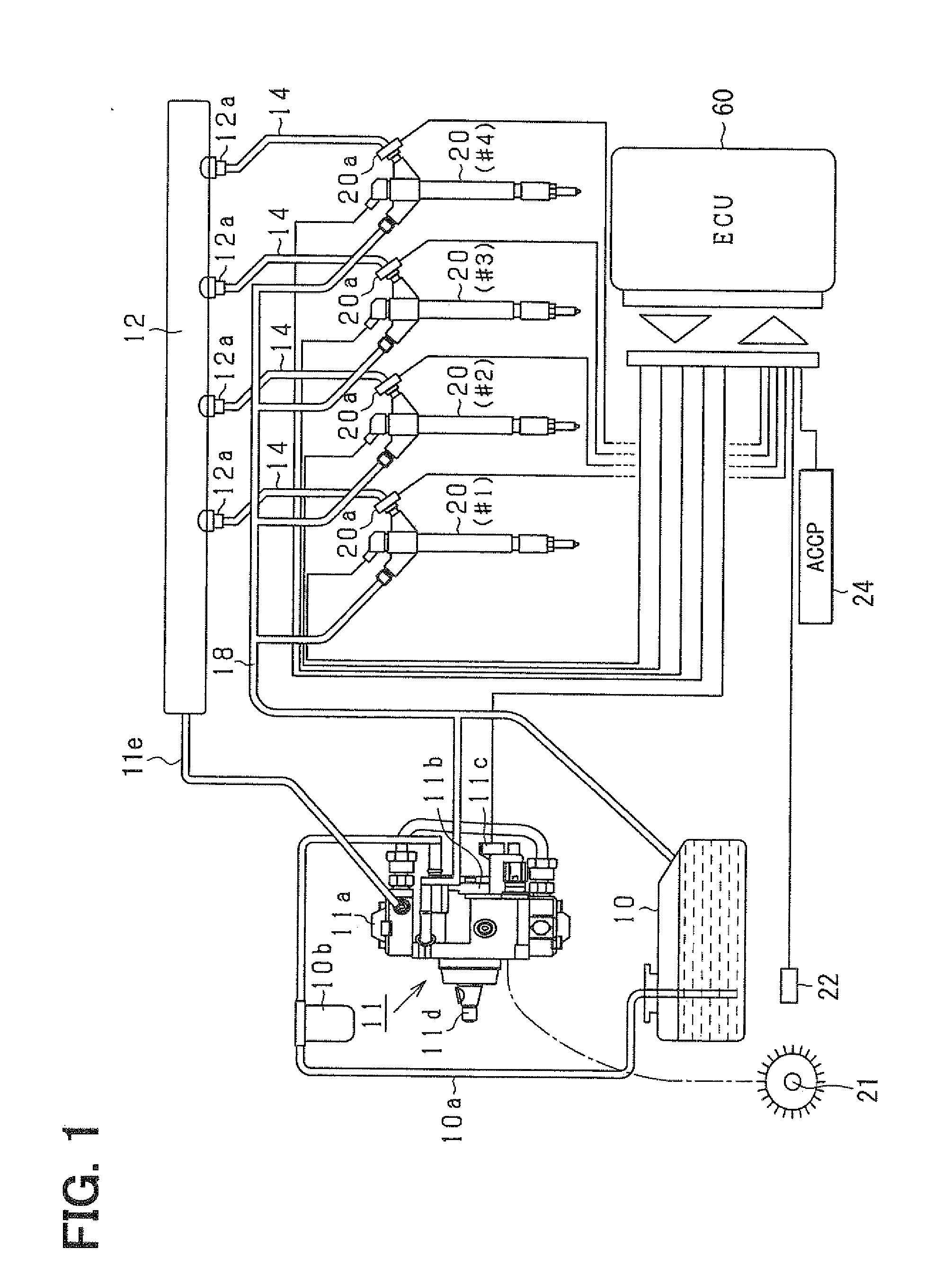
[0073]A fuel injection device according to the present invention is mounted, for example, in a common rail fuel injection system (a high-pressure injection fuel supply system) for controlling a reciprocating diesel engine as an engine for an automobile. That is, like the device described in Patent document 1, the device according to the present embodiment is also a fuel injection device for a diesel engine used to perform injection supply (direct injection supply) of high-pressure fuel (for example, light oil at injection pressure of 1000 atmospheres or higher) directly into a combustion chamber in an engine cylinder of the diesel engine (an internal combustion engine).

[0074]First, an outline of the common rail fuel injection system according to the present embodiment will be explained with reference to FIG. 1. It is assumed that the engine according to the present embodiment is a multi-cylinder engine (for example, an in-line four-cylinder engine) for a four-wheeled vehicle. The in...

second embodiment

[0146]Next, the present invention will be described.

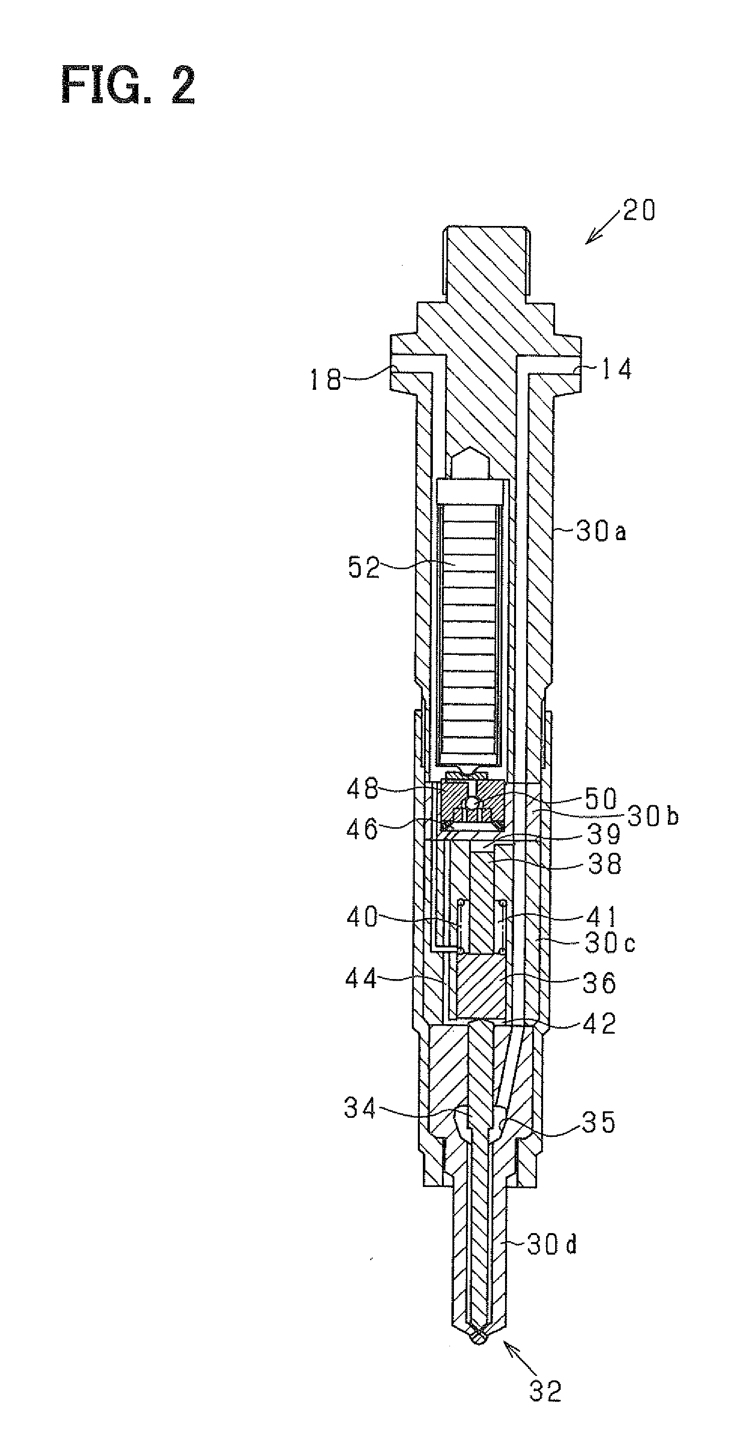
[0147]In the second embodiment, concerning the injection rate waveform of the actual injection, various timings other than the injection start timing and the injection rates at the timings are also sensed based on the output of the above-described fuel pressure sensor 20a. The injection rate waveform concerning the injection is sensed based on the sensed timings and the injection rates. In addition, the operation current signal, i.e., the operation signal (the actuator operation signal) to the above-described piezoelectric element 52 (FIG. 2), for approximating the sensed injection rate waveform to the above-mentioned basic waveform (part (c) of FIG. 6) is calculated. However, in the present embodiment, the calculated operation current signal is not set during execution of the predetermined injection executed on the occasion of the calculation. That is, the thus-calculated operation current signal is set as a command concerning a c...


PUM


Abstract

A fuel injection control device (ECU) for controlling injection supply of fuel to an engine is applied to an injector that has a valve body formed with a fuel injection hole, a needle accommodated in the valve body for opening and closing the injection hole, and a piezoelectric element for driving the needle such that the needle reciprocates and that can continuously adjust an injection rate in accordance with an injection command signal to the piezoelectric element. The fuel injection control device senses a fuel pressure waveform indicating a transition of fuel pressure fluctuation accompanying a predetermined injection of the injector based on an output of a fuel pressure sensor and calculates an injection command signal for approximating a predetermined injection parameter concerning the predetermined injection to a reference value of the parameter based on the sensed fuel pressure waveform.

Description

CROSS REFERENCE TO RELATED APPLICATION[0001]This application is based on and incorporates herein by reference Japanese Patent Application No. 2007-227115 filed on Aug. 31, 2007.BACKGROUND OF THE INVENTION[0002]1. Field of the Invention[0003]The present invention relates to a fuel injection control device that is applied to a fuel supply system injecting fuel through a predetermined injector and that controls a fuel injection characteristic of the system.[0004]2. Description of Related Art[0005]As one of technologies for improving emission of an in-vehicle diesel engine or the like, there is a known technology (high-pressure injection) for injecting fuel, which is pressurized to high pressure, directly into a cylinder through an injector. In recent years, a common rail fuel injection system (for example, a system described in Patent document 1: JP-A-H10-220272) has come to attract attention as a fuel injection system realizing the high-pressure injection. In the system, the fuel pump...

Claims


Application Information

Patent Timeline
Patent Type & Authority Applications(United States)
IPC IPC(8): F02D41/30
CPCF02D41/2096F02D41/40F02D2200/0602Y02T10/44F02M57/005F02M63/0225F02M37/0041Y02T10/40
Inventor NAKATA, KENICHIROISHIZUKA, KOJI
Owner DENSO CORP
Why Eureka
Try Eureka