
Method and monitoring apparatus for automated surveillance of a wind turbine and a method for creating a linear model

a monitoring apparatus and automated surveillance technology, applied in the direction of instruments, mechanical roughness/irregularity measurements, mechanical measuring arrangements, etc., can solve the problems of inability to accurately indicate, costly damage, inaccurate constant limit alarms, etc., to reduce the number of measurement values which have to be considered for monitoring, and reduce the flow of test data

Inactive Publication Date: 2012-07-19
SIEMENS AG
View PDF9 Cites 22 Cited by
  • Summary
  • Abstract
  • Description
  • Claims
  • Application Information

AI Technical Summary

Benefits of technology

"The present invention provides a monitoring apparatus and methods for an improved automated surveillance of a wind turbine. The invention involves creating linear models that represent different status parameters of the wind turbine and measuring the relevant measurement variables. These models are designed to indicate the status of the wind turbine or parts of it. The invention uses a combination of linear models and momentary measurement values to generate wind turbine status information. The linear models are created or retrieved based on the experienced or known physical correlation of the measurement variables. The invention provides a more accurate and reliable method for surveillance of wind turbines, particularly for identifying defect components."

Problems solved by technology

Yet if the wind turbine is operating in a very cold ambient atmosphere, the alarm may never be triggered because the respective temperature limit may not be exceeded, even if the bearings have run out of lubricant.
Thus constant limit alarms are often inaccurate, that is, they are often too imprecise to indicate whether something is malfunctioning or not.
Alarms based on constant limits may produce many false alarms and over time, people may tend to ignore the alarm system, which in turn can lead to costly damages.

Method used


Image

  • Method and monitoring apparatus for automated surveillance of a wind turbine and a method for creating a linear model
  • Method and monitoring apparatus for automated surveillance of a wind turbine and a method for creating a linear model
  • Method and monitoring apparatus for automated surveillance of a wind turbine and a method for creating a linear model

Examples


Embodiment Construction

[0050]In the drawings, like reference numbers refer to like objects throughout. Objects in the diagrams are not necessarily drawn to scale.

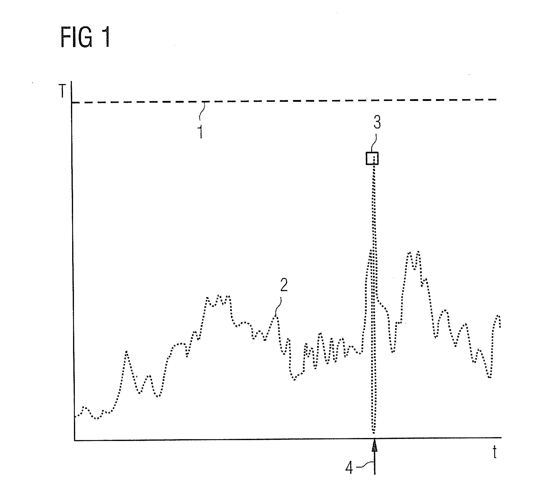
[0051]FIG. 1 shows in a curve diagram the principal of operation of a fault detection system for a wind turbine according to the state of art. The curve diagram comprises one curve displaying values of a reference measurement 2 that represents a physical quantity relevant for the status of a wind turbine, e.g. the temperature T of a generator bearing, over time t. According to the state of the art of fault detection a constant alarm limit 1 is defined for the generator bearing temperature 2. In FIG. 1 the constant alarm limit 1 is depicted as dotted line. In the situation showed in FIG. 1 no alarm is triggered, because the generator bearing temperature 2 does not exceed the alarm limit 1. Even around the time of lubrication 4 when the generator bearing temperature 2 reaches a very high value peak 3, thus indicating an obvious problem, no alarm is...


PUM


Abstract

A method for automated surveillance of at least one wind turbine is provided. A linear model is created or retrieved, which represents at least one status parameter of the wind turbine and which includes a plurality of linear coefficients and a measurement variable. The values of the linear coefficients are determined based on test measurement values for the measurement variable and the status parameter of the wind turbine. Momentary measurement values are repeatedly captured for the measurement variables and the status parameter of the wind turbine. A momentary reference value of the status parameter is determined based on the momentary measurement values for the measurement variables by using the linear model. Wind turbine status information is generated based on the deviation of the momentary measurement value from the corresponding momentary reference value of the status parameter. A monitoring apparatus and a method for creating a linear model are disclosed.

Description

CROSS REFERENCE TO RELATED APPLICATIONS[0001]This application claims priority of European Patent Office application No. 11151130.9 EP filed Jan. 17, 2011. All of the applications are incorporated by reference herein in their entirety.FIELD OF INVENTION[0002]The invention relates to a method and a monitoring apparatus for automated surveillance, in particular fault detection, of a wind turbine and a method for creating a linear model for use in the method or the monitoring apparatus.BACKGROUND OF INVENTION[0003]Today most automated surveillance of wind turbines and fault detection in particular is based on checking whether measurement values, which are indicating operational properties of the wind turbines, exceeding pre-defined constant limits. As soon as a measurement value exceeds its respective limit, an alarm is triggered. For example, if the temperature of the generator bearings of a wind turbine exceeds a certain temperature limit, an alarm is triggered and the wind turbine ma...

Claims


Application Information

Patent Timeline
Patent Type & Authority Applications(United States)
IPC IPC(8): G06F19/00G06F17/10
CPCF03D11/0091Y02E10/722F05B2260/84F03D17/00
Inventor FREDERIKSEN, DAN
Owner SIEMENS AG
Learn More