
Micro vapor chamber

a technology of vapor chamber and micro-vapor chamber, which is applied in the direction of basic electric elements, semiconductor devices, lighting and heating apparatus, etc., can solve the problems of increasing the performance of electronic elements, increasing the heat generation of electronic elements during their operation, and affecting the cooling of electronic products, etc., and achieves high thermal conductivity efficiency.

Active Publication Date: 2012-07-26
ASIA VITAL COMPONENTS SHENZHEN CO LTD
View PDF7 Cites 17 Cited by
  • Summary
  • Abstract
  • Description
  • Claims
  • Application Information

AI Technical Summary

Benefits of technology

[0013]In order to solve the above problems, the primary objective of the present invention is to provide a micro vapor chamber which can be made compact. Another objective of the present invention is to provide a micro vapor chamber, in which liquid-vapor phase circulation of a working fluid is improved greatly.
[0015]By the protrusions of the condensing region, the vapor-phase working fluid can be quickly condensed in the condensing region and collected to form droplets to flow back to the liquid-collecting regions and the evaporating region. In this way, the liquid-vapor phase circulation of the working fluid in the micro vapor chamber can be improved greatly.

Problems solved by technology

However, the increased performance of the electronic element inevitably generates more heat during its operation.
Thus, it is an important issue to dissipate the heat generated by the electronic apparatus or system in order to improve its performance.
The increase in heat flux may cause a challenge to the cooling of an electronic product and make the electronic elements to be overheated at different times and locations.
As a result, the electronic elements of the electronic product may suffer damage or break down.
However, since the thickness of upper and lower walls of a micro vapor chamber is small (<1.5 mm), the portions of the above-mentioned micro vapor chamber in which no copper posts, sintered posts or foamed posts are supported may collapse or cave.
As a result, the flatness and strength of the micro vapor chamber cannot be maintained in an ideal value, which makes the compact design of the micro vapor chamber difficult.
Thus, the reflow rate of the working fluid is insufficient.
On the other hand, since the reflow rate of the working fluid is small, the working fluid may dry out in the evaporating region to greatly deteriorate the thermal-conducting efficiency of the whole vapor chamber.
If the number or density of the wick structure (either made of sintered posts or meshes) is increased to improve the reflow rate of the working fluid, such a sintered or meshed wick structure will make the vapor chamber unable to be further compact.
(1) the reflow rate of the working fluid is too slow;
(2) its thermal-conducting efficiency is poor; and
(3) the compact design thereof is difficult.

Method used


Image

  • Micro vapor chamber
  • Micro vapor chamber
  • Micro vapor chamber

Examples


Embodiment Construction

[0031]The above objectives and structural and functional features of the present invention will be described in more detail with reference to preferred embodiments thereof shown in the accompanying drawings

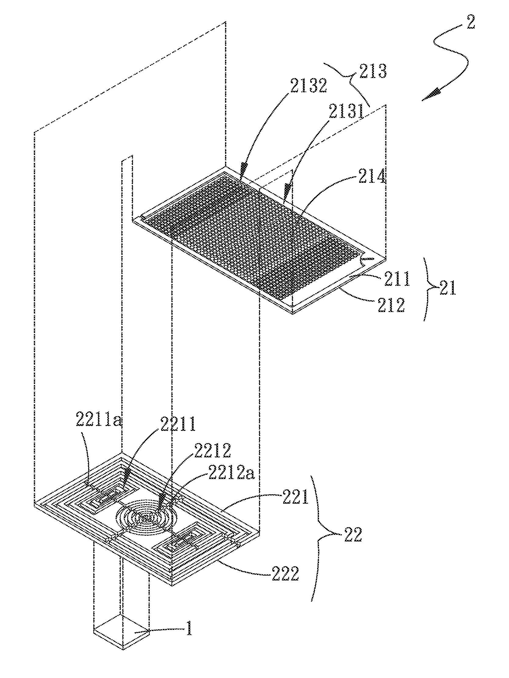
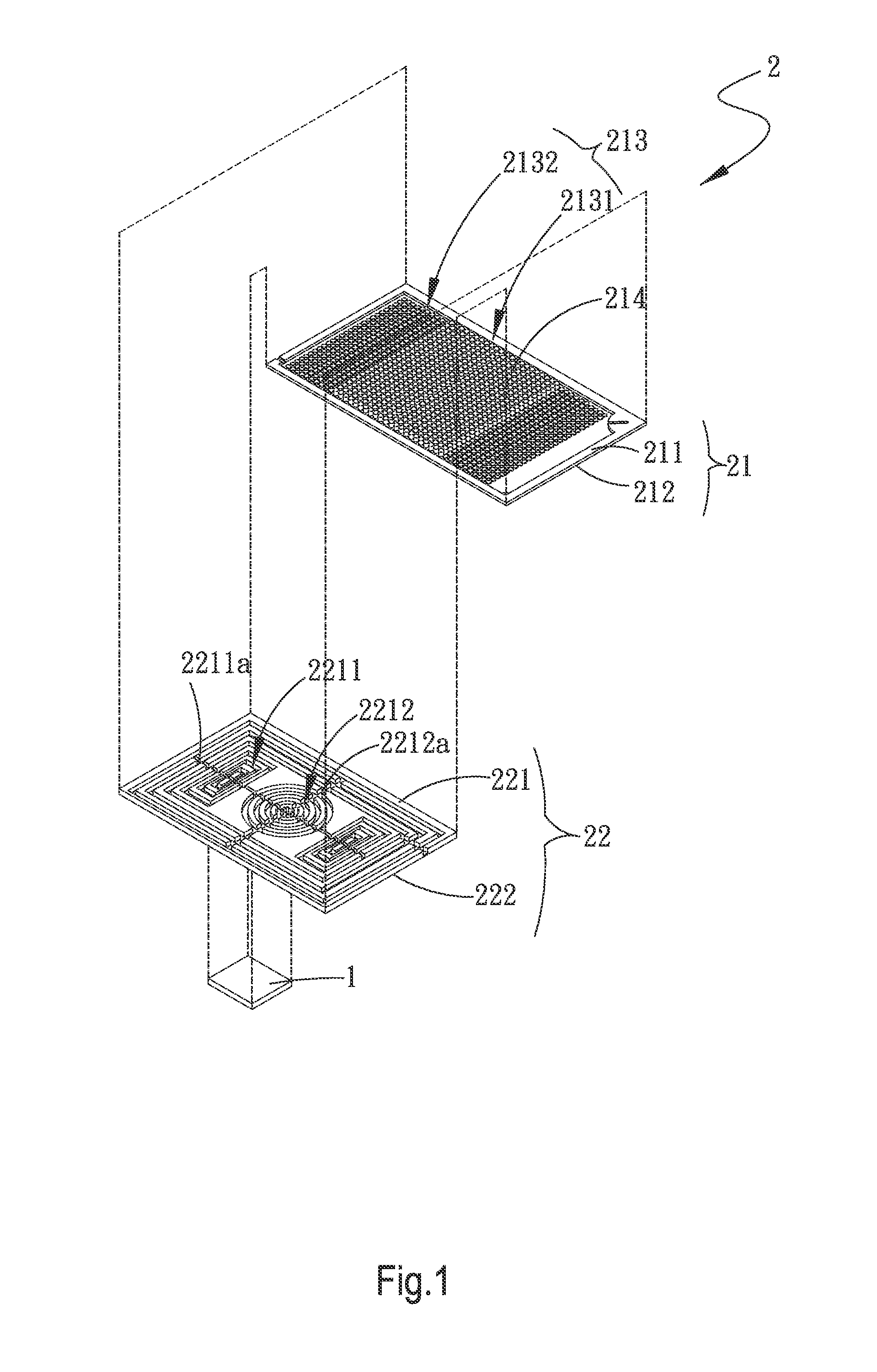
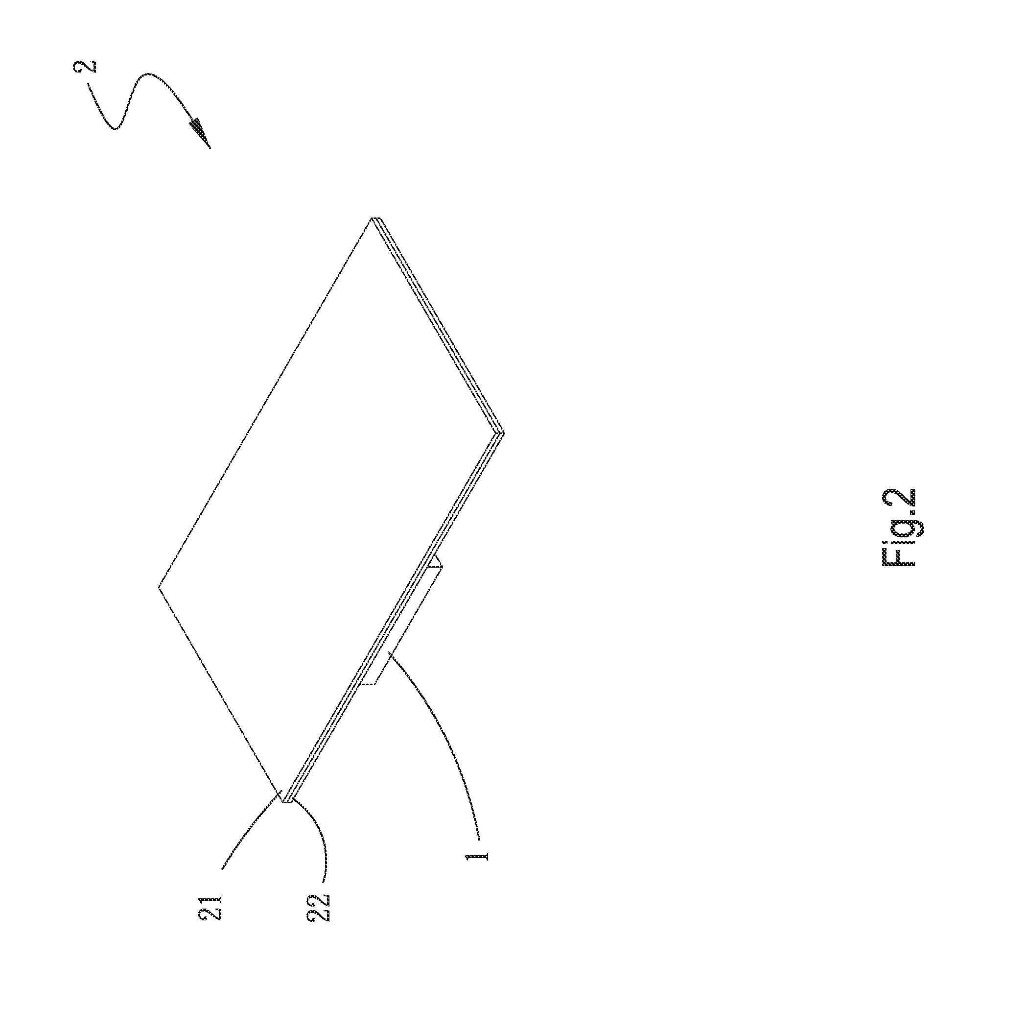
[0032]FIGS. 1, 2, 3 and 3a are an exploded perspective view, an assembled perspective view and two cross-sectional views of the first embodiment of the micro vapor chamber of the present invention respectively. As shown in these figures, the micro vapor chamber 2 of the present invention is configured to cooperate with at least one heat source 1. The micro vapor chamber 2 comprises a first plate 21 and a second plate 22.

[0033]The first plate 21 has a first side surface 211 and a second side surface 212. The first side surface 211 has at least one condensing region 213. The condensing region 213 has a plurality of protrusions 214. The protrusions 214 may have different diameters. As shown in FIG. 3a, the distal end of each protrusion 214 may be formed into a sharp end to facilitate...


PUM


Abstract

A micro vapor chamber includes a first plate and a second plate. The first plate has a condensing region constituted of a plurality of protrusions. The second plate has a plurality of liquid-collecting regions and an evaporating region. The condensing region is located to correspond to the liquid-collecting regions and the evaporating region. The first plate is arranged to cover the second plate. The condensed working fluid are quickly collected on the protrusions to flow back to the evaporating region, thereby improving the liquid-vapor phase circulation of the working fluid in the micro vapor chamber greatly.

Description

[0001]This application claims the priority benefit of Taiwan patent application number 100102802 filed on Jan. 26, 2011.BACKGROUND OF THE INVENTION[0002]1. Field of the Invention[0003]The present invention relates to a micro vapor chamber, and in particular to a micro vapor chamber in which a condensing region is provided with protrusions for allowing condensed working fluid to be quickly collected thereon so as to accelerate the flowing of the condensed working fluid back to an evaporating region. By this structure, the efficiency of liquid-vapor phase circulation of the working fluid in the micro vapor chamber is improved greatly.[0004]2. Description of Prior Art[0005]Currently, electronic apparatuses are gradually made to be more and more compact. Although the dimension of a semiconductor forming an electronic element is reduced, the performance of the semiconductor and the formed electronic element has to be increased. However, the increased performance of the electronic element...

Claims


Application Information

Patent Timeline
IPC IPC(8): F28D15/02
CPCF28D15/0266F28D15/046H01L23/427H01L2924/0002H01L2924/00
Inventor YANG, HSIU-WEICHANG, FU-KUEI
Owner ASIA VITAL COMPONENTS SHENZHEN CO LTD
Learn More