Hydrodynamic bearing assembly and motor including the same

Inactive Publication Date: 2012-07-26
SAMSUNG ELECTRO MECHANICS CO LTD
View PDF7 Cites 10 Cited by
  • Summary
  • Abstract
  • Description
  • Claims
  • Application Information

AI Technical Summary

Benefits of technology

[0013]An aspect of the present invention provides a hydrodynamic bearing assembly in which coupling force between a thrust plate and

Problems solved by technology

However, when a bonding process is performed in order to couple the thrust plate to the shaft, a bonded contact area is limited, such that sufficient coupling force is

Method used


Image

  • Hydrodynamic bearing assembly and motor including the same
  • Hydrodynamic bearing assembly and motor including the same
  • Hydrodynamic bearing assembly and motor including the same

Examples


Example

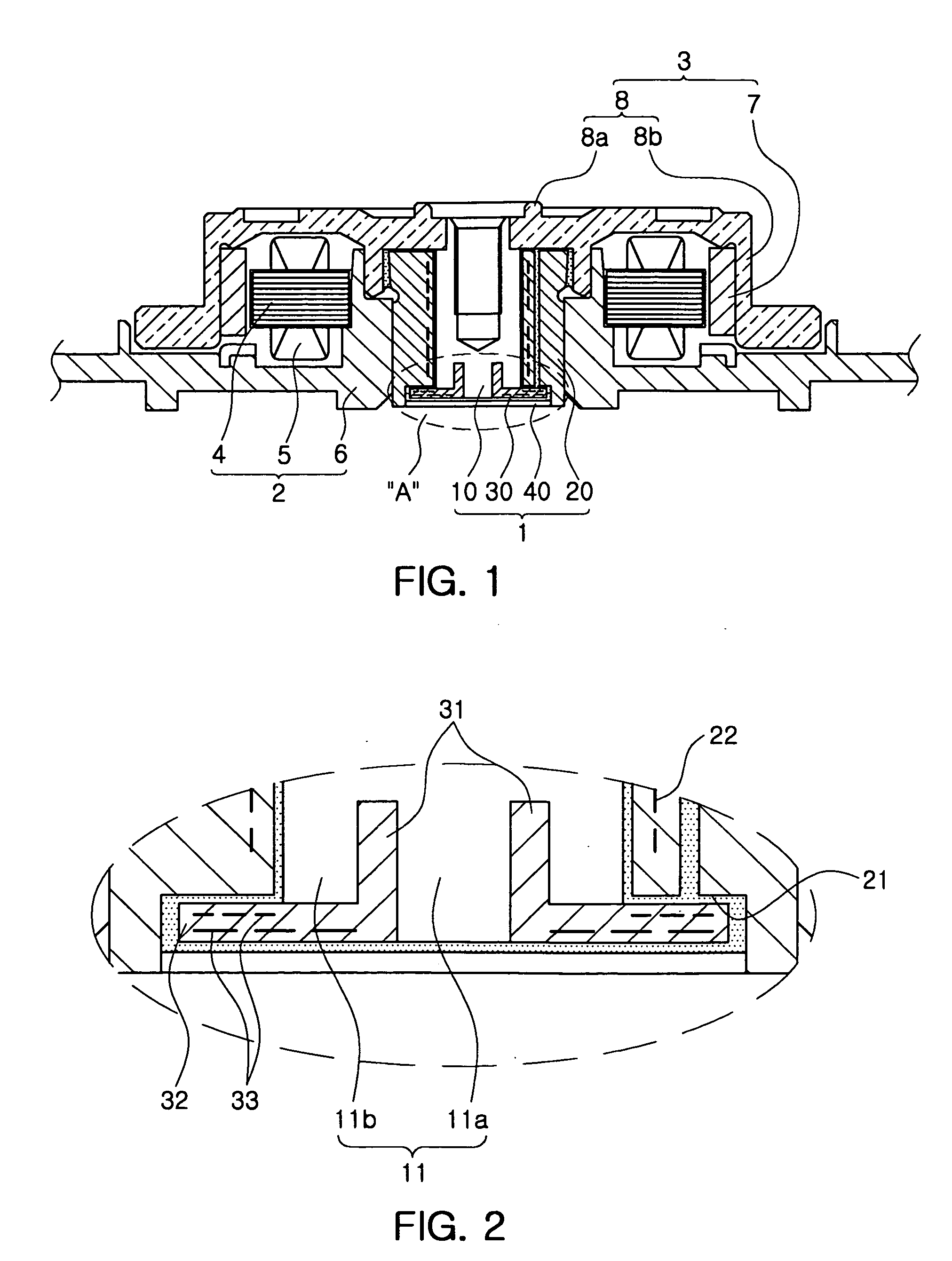
[0073]FIG. 3 is a cross-sectional view schematically showing a first embodiment of a modified thrust plate according to an exemplary embodiment of the present invention.

[0074]Referring to FIG. 3, only one extension part 31 according to the exemplary embodiment of the present invention may be formed at the thrust plate 30; however, a plurality of extension parts 31 having different diameters may also be formed. That is, the plurality of extension parts 31 having a concentric circle may be formed at the thrust plate 30, such that the coupling part 11 may include a first coupling part 11a contacting an innermost surface of the extension part 31, a second coupling part 11b contacting an outermost surface thereof, and a third coupling part 11c contacting inner / outer surfaces between the innermost and outermost surfaces.

[0075]Therefore, a coupling area between the thrust plate 30 and the shaft 10 may be increased, as compared to the case in which a single extension part 31 is formed.

[0076...

Example

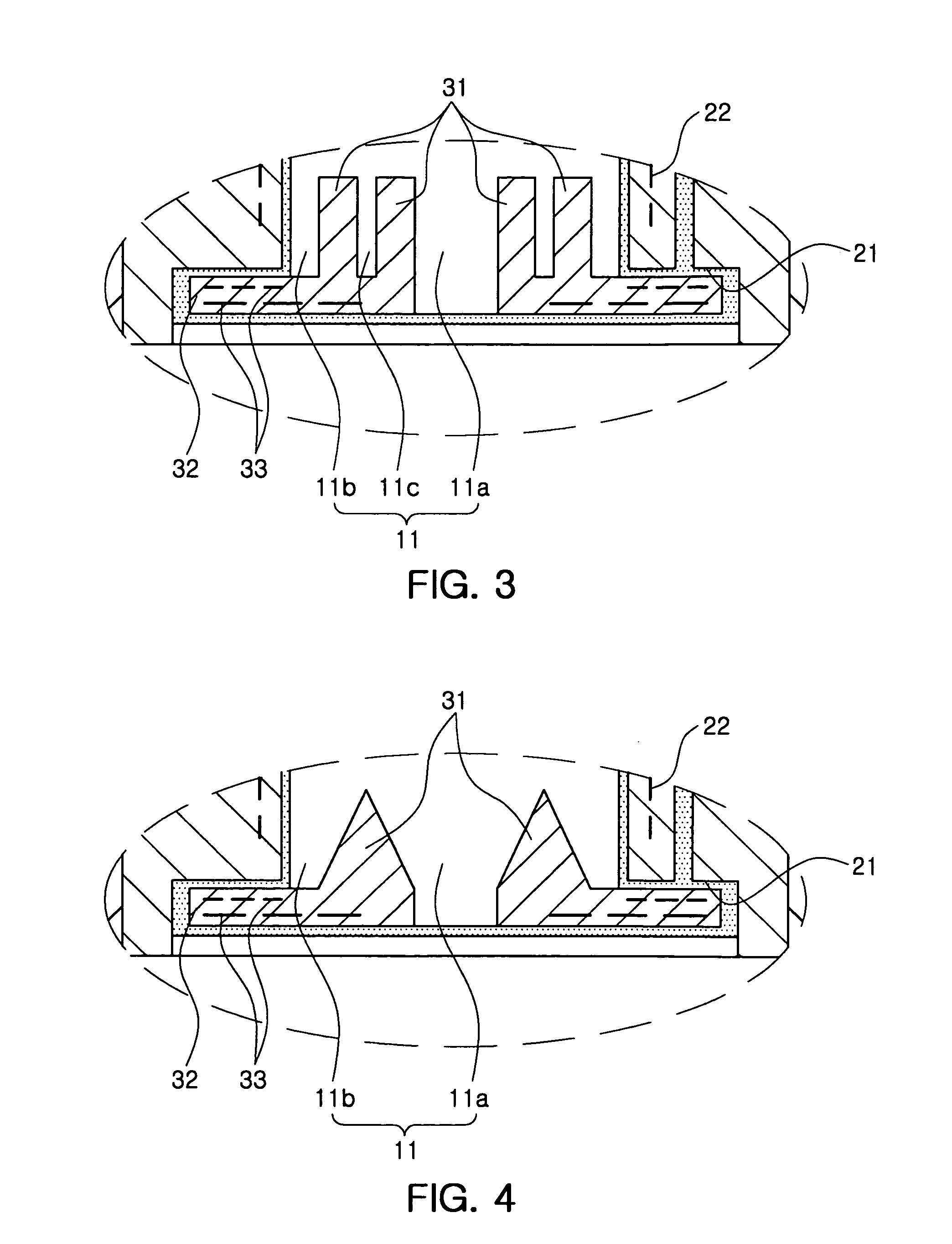
[0077]FIG. 4 is a cross-sectional view schematically showing a second embodiment of a modified thrust plate according to an exemplary embodiment of the present invention.

[0078]Referring to FIG. 4, the extension part 31 may be formed horizontally with the axial direction; however, at least one of the inner and outer surfaces of the extension part 31 may also be formed to be tapered. That is, at least one of the inner and outer surfaces of the extension part 31 may be formed to be inclined or may be formed to be curved.

[0079]Therefore, the thrust plate 30 may be inserted into the shaft 10 along a tapered surface of the extension part 31 during the coupling between the thrust plate 30 and the shaft 10, whereby the coupling therebetween is facilitated.

Example

[0080]FIG. 5 is a cut-away perspective view schematically showing a third embodiment of a modified thrust plate according to an exemplary embodiment of the present invention.

[0081]Referring to FIG. 5, the extension part 31 may be continuously formed at the thrust plate 30 in the circumferential direction; however, the extension part 31 may also be formed in an interrupted manner in the circumferential direction. That is, a plurality of fan-shaped extension parts 31 may be formed in the circumferential direction.

[0082]Meanwhile, when the extension part 31 is formed in an interrupted manner in the circumferential direction, the coupling part 11 of the shaft 10 may have a shape corresponding to that of the extension part 31.

[0083]Therefore, a advantage in which the thrust plate 30 may completely be dependent on the rotational driving of the shaft 10 is generated.

[0084]That is, the rotational force of the shaft 10 may be transferred to the thrust plate 30 by a structural shape of the ex...


PUM


Abstract

There is provided a hydrodynamic bearing assembly including: a sleeve having a shaft inserted thereinto and supported thereby; a thrust plate coupled to one end of the shaft; an extension part formed at the thrust plate to be extended in an axial direction so as to be coupled to the shaft; and a coupling part formed at the shaft to contact an inner surface of the extension part so as to be coupled to the extension part.

Description

CROSS-REFERENCE TO RELATED APPLICATIONS[0001]This application claims the priority of Korean Patent Application No. 10-2011-0007273 filed on Jan. 25, 2011, in the Korean Intellectual Property Office, the disclosure of which is incorporated herein by reference.BACKGROUND OF THE INVENTION[0002]1. Field of the Invention[0003]The present invention relates to a bearing assembly and a motor including the same, and more particularly, to a bearing assembly in which a structure and a shape of a shaft or a thrust plate are changed to improve coupling force and reduce assembly defects, and a motor including the same.[0004]2. Description of the Related Art[0005]A motor generating driving force has been mounted in a hard disk drive (HDD) or an optical disc drive (ODD), both of which being computer information storage devices.[0006]The motor may provide a space, in which a shaft may rotates, by a bearing. As the bearing, a hydrodynamic bearing, or the like, may be used.[0007]Meanwhile, in order to...

Claims


Application Information

Patent Timeline
IPC IPC(8): F16C32/06H02K7/08
CPCF16C17/107F16C41/008H02K7/085F16C2370/12F16C32/06F16C17/04H02K5/16
Inventor NOH, JEE AELEE, TA KYOUNG
Owner SAMSUNG ELECTRO MECHANICS CO LTD
Why Eureka
Try Eureka